BATTERY: INDUSTRIAL CHARGER & PROGRAMMABLE POWER SOURCE
With the democratization of mobile devices, the drop of manufacturing cost of batteries, as well as the growing awareness on environmental topics issues, the technology of batteries and chargers has witnessed a tremendous breakthrough in the past few decades; numerous of new batteries have seen the light of day, and innovative charger applications are born as accompaniment.
From Electric Vehicle Charging (EV Charging) infrastructure to Energy Storage System (ESS), the modern chargers are utilized in numerous different sectors nowadays and are pushing the society further towards the more sustainable and renewable energy options.
MEAN WELL INDUSTRIAL CHARGERS
MEAN WELL is the global leading manufacturer of standard Power Supplies in the market. With over 40 years of experience in the development and production of Power Supplies, MEAN WELL offers a complete range of charging solutions to diverse fields, including the household, commercial and public sectors.
HOW CHARGER IS DIFFERENT FROM REGULAR POWER SOURCE
While common Power Supplies are designed to provide a fixed and constant DC voltage, chargers require a more complex design with different charging phases to assure the longevity of batteries and safety during operation.
To meet the specific charging needs of different types of batteries, industrial chargers are generally designed with several charging phases, including principally a boost voltage-constant current phase, a constant voltage phase, and a float voltage phase.
More advanced industrial chargers use a microcontroller (MCU) design, which detects the charging status of the connected batteries and allows further adjustment between different charging phases.
Nevertheless, it does not mean that chargers are the only option for charging applications nowadays. Advanced technology in power supplies has made it possible to adapt a programmable power supply, with adjustable voltage and current, to the specific charging demands in the field too.
HOW TO CHOOSE YOUR CHARGER
Choosing the adequate DC power source for the battery is critical if one wishes to maintain the battery’s performance. In the following paragraphs, we will be listing down a few criteria which are considered essential when it comes to the selection of proper chargers for the system.
A. Battery Charging Profile
Each battery type has its own specific charging needs and requirements. These requirements are normally defined by the battery manufacturer and listed in their specification. Hence it is important to start by identifying the battery charging profile before further diving into choosing the suitable charger. For the 2 most popular battery types used, we listed 2 example charging curves below:
- Lead-Acid Battery requires chargers with minimum 3 charging stages.

Image 1: Three Stages for Lead-Acid Battery
- Lithium-based Battery requires generally chargers with 2 charging stages: first with constant current, followed by constant voltage.
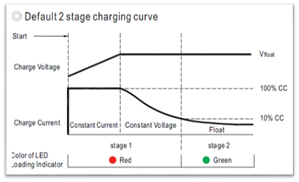
Image 2: Two stages for Lithium-based battery (LiFeP04, LiCoO2)
For more information read our “Lead-acid and lithium battery charging” article.
For more information about selecting the right charger for your battery please refer to our “Selecting a charger from your battery” article.
Tip: MEAN WELL offers a Smart Battery Charging Programmer (SBP-001) which allows users to configure via a user-friendly interface, the charging curve of selected MEAN WELL chargers and power supplies (e.g. Intelligent RCB-1600 charger, HEP-1000 for Harsh environment, ENC…etc.). With SBP-001 programmer, the user can set the output current and voltage to further simulate the charging curve for different batteries.
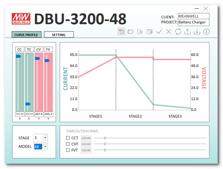
Image 3: Intelligent Charger DBU-3200, configurated via SBP-001 and its user-friendly interface (Click to download)
B. Regulations
According to International Electrotechnical Commission (IEC), numerous regulation standards exist for the purpose of ensuring safety, efficiency, reliability, and interoperability of electrical, electronic, and information technologies; depending on the application of the end device, the mandatory regulations can differ from one to another.
For instance, IEC/EN 60335-1 is the basic requirement for Household appliances’ design, aiming to prevent foreseeable hazards ones could encounter when using the end device. Furthermore, IEC/EN 60335-2-29 defines the requirements in detail for battery chargers intended for household battery charging.
Specific charger applications such as AC EV Charger might require an additional power source to power the auxiliary and communication modules inside the such charger. For these kinds of applications, one has to evaluate on the system level if power supplies with more strict requirements are needed, such as the IEC/EN 61558-1 certification and compliance with OVC III (Overvoltage category III) protection level. Power Supplies with OVC III compliance can be integrated without adding an extra isolation transformer on the input side and gives your products the best out in terms of flexibility and costs in a minimized space. In addition, using such power supplies in AC Charters gives greater flexibility in terms of installation as these would allow the charger to be permanently connected to a distribution panel.
As for chargers intending to power up UPS systems and battery test systems, IEC/EN 62368-1 and IEC/EN 62477 are generally the safety regulations to comply with.
In addition, the standards related to electromagnetic compatibility (EMC) emission and immunity are equally important to take into consideration. In case the charging system is certified according to the IEC/EN 62368-1; the EN 55032 and CISPR 32 standards must be confirmed; in case the system needs to be certified for the IEC/EN 60335-1, the emissions and immunity according to the EN 55014 have to be met. Other major EMC regulations which must be complied with are the IEC/EN 61000-3 and IEC/EN 61000-4.
Therefore, clarifying the specific requirements for safety and EMC regulation standards will greatly facilitate the selection of the battery charger process.
| Safety Regulation No. | MEAN WELL Series |
| EN62368-1 | HDR-15/30/60/100/150 ENC-120/180/240/360 NPB-120/240/360/450/750/1200/1700 RPB-1600 / RCB-1600 / DBR-3200/ DBU-3200 HEP-600C CSP-3000 PHP-3500 RST-10000/ 5000 BIC-2200 TDR-240/480/960 WDR-60/120/240/480 Adapter Charger: GC30/120/160/220/330 |
| OVC III (based on EN61558) | HDR-15/30/60/100/150 *PHP-3500 |
| OVC III (based on EN62368) | IRM-30/45/60/90 |
| EN60335-2-29 / EN60335-1 | NPB-120/240/360/450/750/1200/1700 |
| EN60335-1 | IRM-60/*90 *PHP-3500 |
*=Regulation Designed Ready, NRE needed by users request
C. Installation
The working environment and condition are essential to the reliability and lifetime of both battery and charger; engineers must take into consideration the eventual working and storage condition of the battery charger to further choose an adequate model for the design.
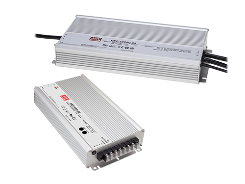
For instance, chargers designed as 5G vibration-proof are more suitable for installation located in a mobile device. E.g., wheelchair, E-bike, mobile working station, camper van…etc. Whereas waterproof and dust-resistant IP67 chargers and power supplies are generally recommended for application under humid and dusty environment, both indoor and outdoor.
On the other hand, it is not to forget that the working temperature is equally important to the longevity of battery charger and battery as the other working conditions mentioned earlier. Therefore, one should think about selecting a power source with adequate thermal dissipation design (e.g., convention cooling, forced air flow, conducted colling, water cooling…etc..) for the system too.
Last but not least, the selection of battery charger is sometime limited by the available space or specific installation method too; a 19-inch rack cabinet will probably need an 1U Battery Charger (e.g., 1U-tall RCB-1600) to save space and a DIN Rail cabinet will most likely adapt a DIN RAIL power source (e.g., HDR series with OVC III protection)…etc.
Future postings and articles:
In the upcoming future, MEAN WELL will also share its knowledge regarding the booming Energy Storage System (ESS) field. For instance, how to use MEAN WELL Chargers (programmable 67~400VDC) in a High Voltage Direct Current (HVDC) application, as well as the know-how on digital communication protocols (e.g., PMbus and CANbus), which can further perform voltage and current control for the Energy sector.
LEARN MORE ABOUT CHARGING POWER SUPPLIES
Explore our blog for insightful technical notes about Charging Applications.
Got questions?
Look at the section below to find the most frequently asked questions (with answers)
we received in Charging Applications.
The GTIN number can be found directly on the www.meanwell.com:

Internally, IRM series has the following AC fuses, which are implemented on AC/L input:
| IRM-01/02/03 | T1A/L300V |
| IRM-05/10/15/20/30 | T2A/L300V |
| IRM-45/60 | T2.5A/L300V |
| IRM-90 | T3.15A/L300V |
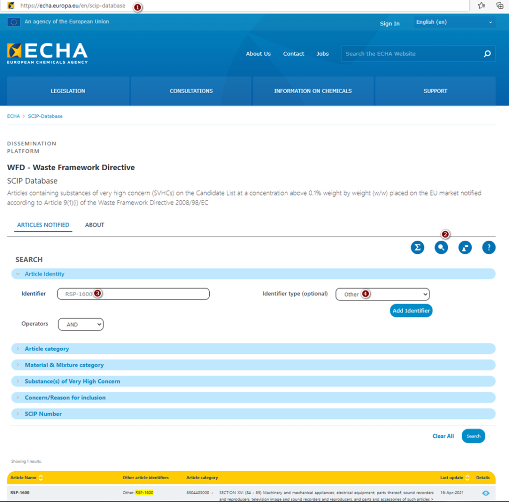
Yes, MEAN WELL products are registered in SCIP. To get such information for specific power supply, please follow the steps below:
- Go to https://echa.europa.eu/en/scip-database
- Under SEARCH option, choose „Article Identity” and write down model name e.g. RSP-1600.
- As “Identifier type (optional)”, please chose “Other”
- Click “Search” button
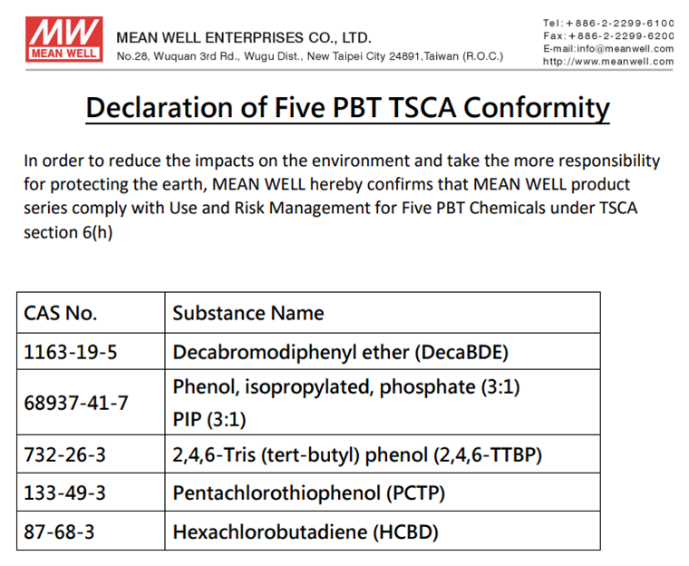
The declaration of Five PBT TSCA Conformity can be found on the last page of Installation Manual e.g. below:
Find the latest news in the MEAN WELL APP


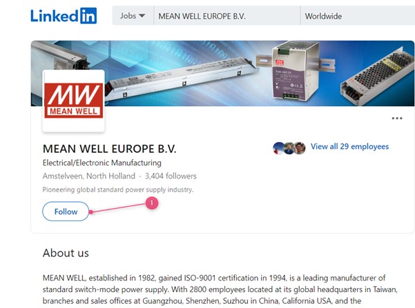
You can follow us on LinkedIn:

Go to:
https://www.linkedin.com/company/meanwell-europe-b-v-/
1. Click follow
And you could install our APP see our FAQ “How to subscribe to MEAN WELL’s newsletter?”
MEAN WELL’s distributor information can be found on Distributor Network-MEAN WELL Switching Power Supply Manufacturer
- Click on the region that you are located
- Select the country you are in
- Click on the search button
- Scroll down to see our local distribution channels
- Look for the distributor with a tick for the product group that you are looking for

MEAN WELL has the largest distribution network for serving your small and medium demand Power Supplies. You can find all MEAN WELL’s distribution channels on Distributor Network-MEAN WELL Switching Power Supply Manufacturer.
OEM’s which have no sales channel for MEAN WELL products yet can contact us via the “Contact Us” form on this website.
MEAN WELL’s discontinued product schedule and End of Life products are normally updated 2 times per year, in January and in July and are published on www.meanwell.com. See FAQ “Where can I find MEAN WELL’s discontinued product schedule and End of Life information? “
The normal procedure for E.O.L. is:
- The product or series is announced in the Discontinued product list in January or July and announced as NRND (Not Recommend for New Design)
- 6 months later the lead time of the product or series will increase +30 days, the price will increase as well.
- Another 6 months later, the lead time will increase another +30 days (so + 60day compared to the original lead time), the price will increase again.
- Another 6 months later, the lead time will increase another +30day (so +90 days compared to the original lead time) and the price will increase again and additionally there will be a MOQ of 200pcs (and steps of 100 for higher quantities)
- After another 6 months the last buy is announced on the website. This will be the last opportunity to place an order for this product or series.
In total MEAN WELL’s End of Life, procedure will take 2 years. However, there are situations for instance that certification is expired, or some components can no longer be obtained by the market which will force to accelerate the EOL schedule. Therefore, it is always highly recommended from the moment that a product is on the discontinued list to design in one of our new generation products. If need any advice to this, please use the “Contact Us” function on this website.
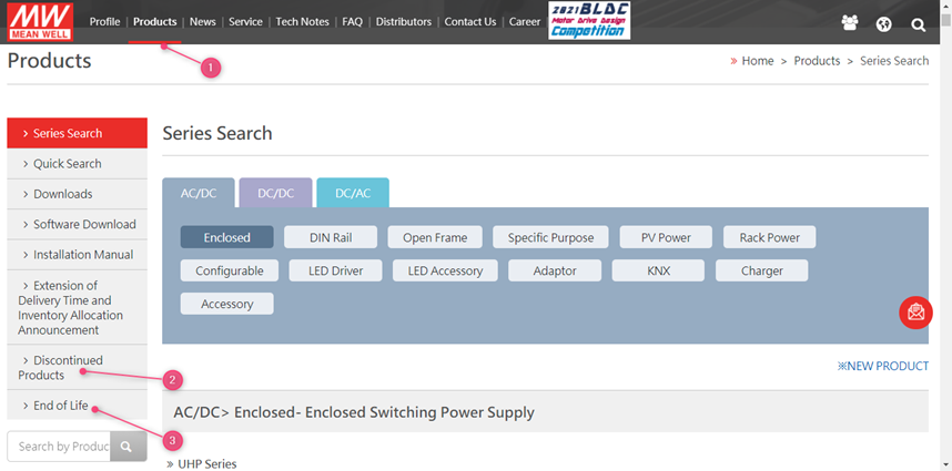
MEAN WELL’s discontinued product schedule and End of Life products are normally updated 2 times per year, in January and in July. To see the full list, go to www.meanwell.com
1. Click on products
2. Click on Discontinued products for the schedule for the EOL schedule
Click on EOL for the MEAN WELL products which are End Of Life
You can use the “Contact Us” function on this website
MEAN WELL’s website provides you all the basic information about our Power Supplies. This includes company news, product announcements, ISO certificates, Specifications, test report, Certificates, ROHS declarations, Reach declarations and many more.
MEAN WELL’s products can be found on www.meanwell.com
1. Click on products and select the product category
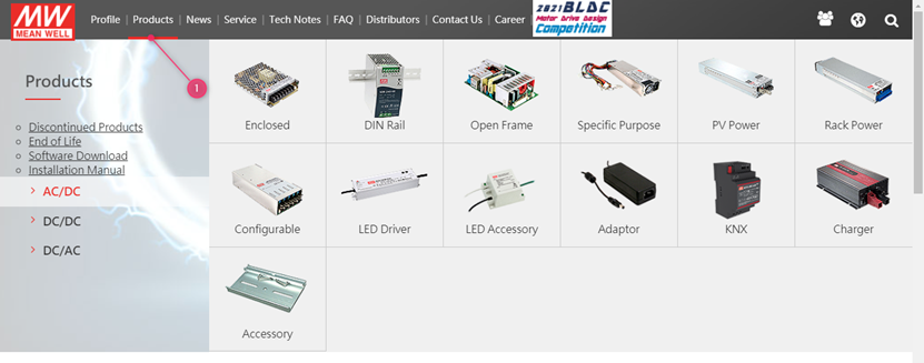
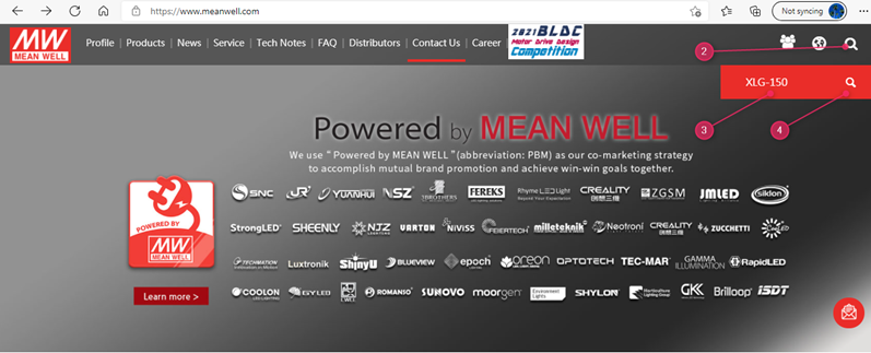
Or in case you already have a part number, you can use the search function on the website:
2. Use the search function on the website to find the right product
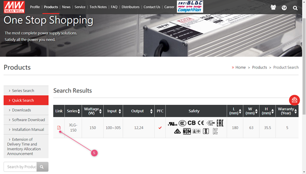
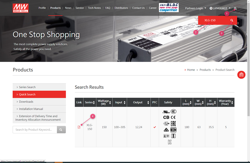
3. Fill in the series number in the search field (do not include the last extensions such as -12 in XLG-150-12)
4. Click the search button
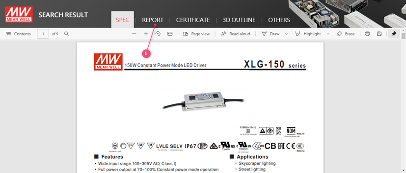
5. Click on the PDF icon to open the specification
MEAN WELL has several charger products, and we suggest choosing them first. Chargers would be more suitable since they are designed for charging applications. Safety and approvals should be taken into account based on the final application. If you are unable to find a proper model in our charger series, our LED CC models can be used as charger. Please choose suitable products after confirming the current and voltage specification on the datasheet of the battery.
All MEAN WELL chargers are preset for lead-acid batteries. For other products that can customize the charging curve (such as ENC / NPB series), customers can customize their charging curve depending on the charging and discharging characteristics of batteries. If you have other requirements, please use the contact us function on this website.
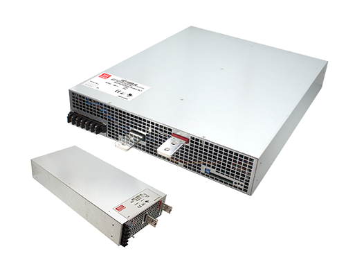
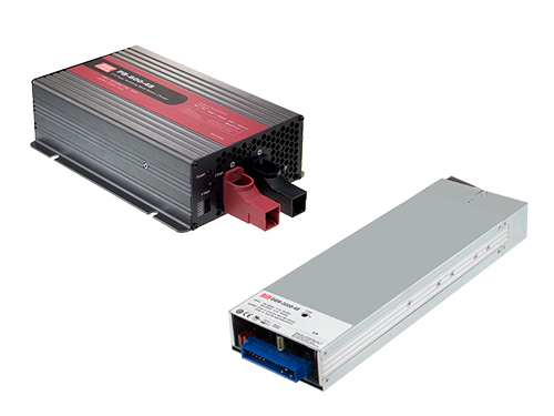
MEAN WELL has launched ENC, HEP-600C, GC, PA, PB, RPB and RCB series for battery charge applications (30~1000W). However, if these models cannot fulfill your requirements, there is an alternative solution. Power supplies with constant current limiting as overload protection are suggested. Charge current varies in battery percentage (full or flat), there is high possibility to trigger overload protection when battery is low, those with overload protection as hiccup or shutdown will stop charging the battery in low battery condition. Yet, using a power supply as charging purpose is considered as overload usage, modification is required. Please Contact Us for the request.
MEAN WELL’s Step files/ 3D files can be found on www.meanwell.com
- Use the search function on the website to find the right product
- Fill in the series number in the search field (do not include the last extensions such as -12 in XLG-150-12)
- Click the search button
- Click on the PDF icon to open the specification
- Click on 3D OUTLINE
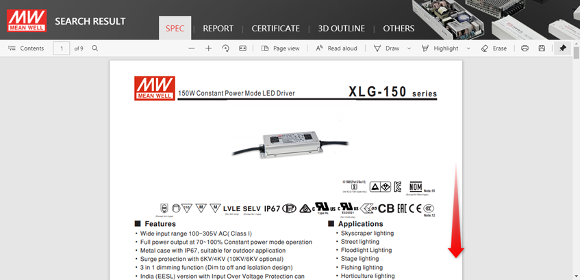
- Click on the model XLG-150-3D to download the step file.

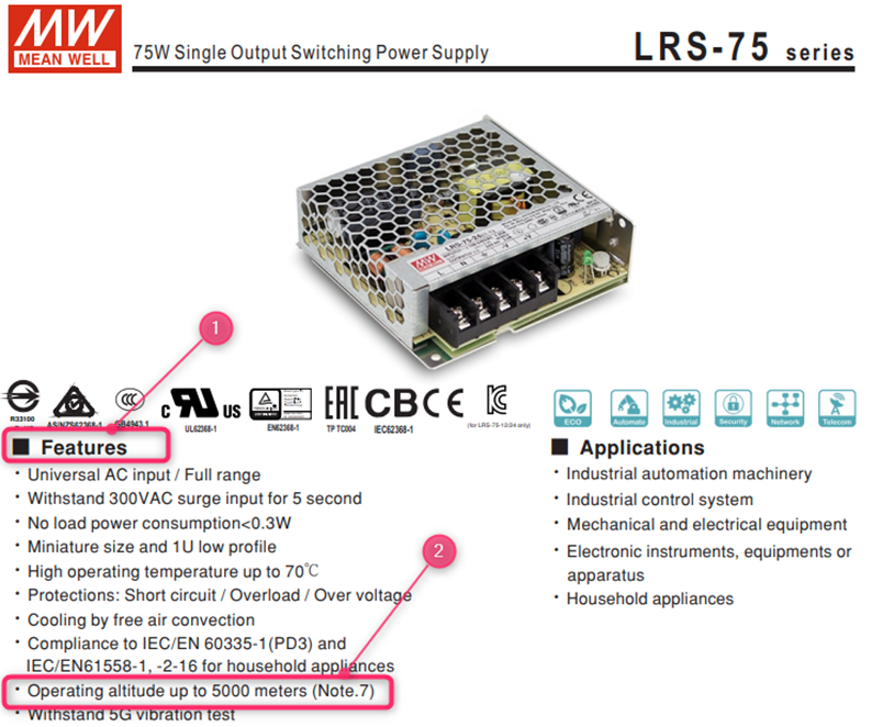
Yes, for power supplies certified >2000m please read the “note” in the spec.
In general, for unpotted models, a derating of 5°C/1000m has to be applied and for potted models, a derating of 3.5°C/1000m has to be applied.
For example LRS-75-24:
The datasheet shows:

The Note. 7 shows:

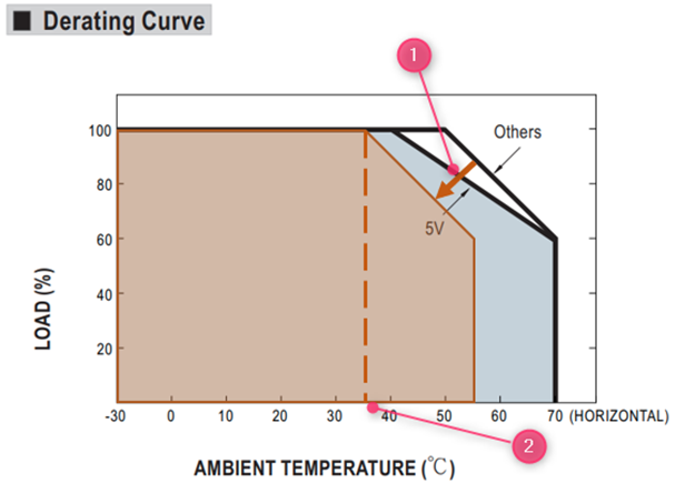
At 5000m the derating curve will need to move 15°C following the arrow (1)
At full load the maximum operating temperature at 5000m will be 35°C shown at (2)
Cooling fans have a relatively shorter lifetime (typical MTTF, Mean Time To Failure, of around 5,000-100,000 hours) compared with other components of power supply. As a result, changing operating method of the fans can extend the operation hours. The most common control schemes are shown as below:nnTemperature control: if the internal temperature of a power supply, detected by a temperature sensor, is over the threshold, the fan will start working at full speed, whereas, if the internal temperature is less than the set threshold, the fan will stop working or run at half speed. In addition, cooling fans in some power supplies are controlled by a non-linear control method whereby fan speed can be changed with different internal temperatures synchronously.nLoad control: if the loading of a power supply is over the threshold, the fan will start working at full speed, whereas, if the loading is less than the set threshold, the fan will stop working or run at half speed.
During safety verification process, the agency will use a stricter standard ±10% (IEC 62368 uses +10%, -10% for the product with AC input rated) of the input voltage range labeled on the power supply to conduct the test. So, operating at the wider input voltage range as specified on the spec. sheet should be fine. The narrower range of input voltage labeled on the power supply is to fulfill the test standard of safety regulation and make sure that users insert input voltage correctly.
PMBus full name is Power Management Bus is an open standard for digital power management. The physical layer is based on I2C, and PM Bus had a set of commands that specifically design for power supply industry. More information can be found in https://pmbus.org/
MEAN WELL Rack Power and intelligent power supply and chargers have optional PMBus solution for example: PHP-3500 and HEP-1000 further the RCP/RSP-1600, UHP-2500 and DPU-3200 have this optional available.
A Controller Area Network (CAN Bus) is a bus standard initially developed for vehicle designed to allow multi-master with priority control without a host computer. The latest version is CAN 2.0 which consists of part A and part B. CAN 2.0A is for standard format with 11-bit identifier, and CAN 2.0B is for extended format with 20-bit identifier. CAN Bus is widely used in Automotive and industrial automation. There are not only 1 but many higher layer protocol such as CANopen, DeviceNet and more.
MEAN WELL CAN Bus product support CAN 2.0B (ISO-11898) with baud rate 250Kbps
MEAN WELL offers optionally CAN bus for PHP-3500, HEP-1000, RCP/RSP-1600, UHP-2500 and DRP/DPU-3200 and DBR/DBU-3200.
Most MEAN WELL power supplies are certified to be operated till 2000m. For some models the certification is valid for a higher altitude, this will be shown on the first page of the power supply under features (1)(2).
Please note that derating is needed at an altitude above 2000m. See FAQ “Do I need to derate my power supply when I used it over 2000m?”
MEAN WELL’s specification shows the absolute values which were verified during design quality verification tests. Those condition are guaranteed by manufacture from quality and warranty perspectives.
When certifying a power supply according to a certain norm, there is normally a requirement described in this standard a certain tolerance which must be considered. (See also FAQ: Why Is The Input Voltage On The Label Different From The Input Voltage In The Spec? For Example, The Specification Shows Is 88~264 VAC While The Label On The Power Supply Says That It Is 100~240VAC?)
The specification shows what is possible, the report and label of the power supply shows what is approved by the certifying body according to the standards.
Besides the difference due to tolerance there might also be another reason why the specification and label/test report show a different temperature. For example, if the power supply needs to be derated at a low voltage input such as 100VAC, the label and test report might show the max temperature at full load based on this low input.
Different standards might have different tolerance requirements and different ranges this could mean that the most conservative value, or multiple values will show up on the label of the power supply.
MEAN WELL’s component self-heating can be found on www.meanwell.com
1. Use the search function on the website to find the right product
2. Fill in the series number in the search field (do not include the last extensions such as -12 in XLG-150-12)
3. Click the search button
4. Click on the PDF icon to open the specification

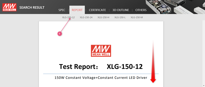
5. Click on report

6. Click on the model and scroll down:

7. The temperature of the critical component can be found in the chapter Reliability Test under item 1 Temperature Rise Test
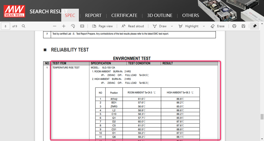
For more details about the component type for each position, please use the Contact Us function on this website.
MEAN WELL’s MTBF can be found on www.meanwell.com
1. Use the search function on the website to find the right product
2. Fill in the series number in the search field (do not include the last 3. extensions such as -12 in XLG-150-12)
3. Click the search button
4. Click on the PDF icon to open the specification

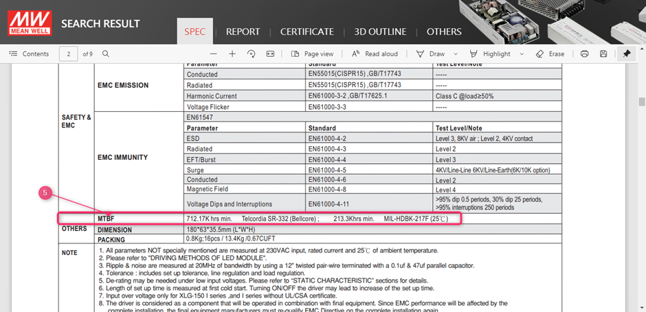
Scroll down in the specification to the bottom of the second page
5. Find the MTBF value in under others:
MEAN WELL’s capacitor lifecycle calculation can be found on www.meanwell.com
1. Use the search function on the website to find the right product
2. Fill in the series number in the search field (do not include the last extensions such as -12 in XLG-150-12)
3. Click the search button
4. Click on the PDF icon to open the specification

5. Click on report
6. Click on the model and scroll down:
7. The Capacitor life cycle calculation is shown on the last page of the report in the chapter Reliability test
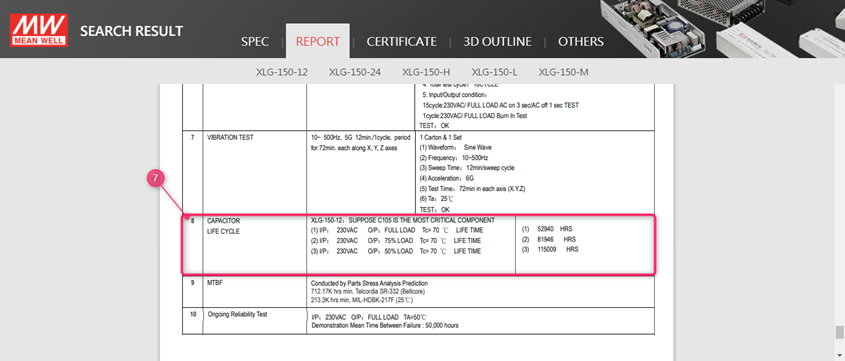
The Capacitor life cycle calculation is considered as the key indicator for the lifetime of the power supply. Please refer to the test report of the power supply on www.meanwell.com for the capacitor life cycle calculation.
As a rule of thumb, every 10dC increase the lifetime will be cut in half and vice versa for every 10dC decrease in temperature.
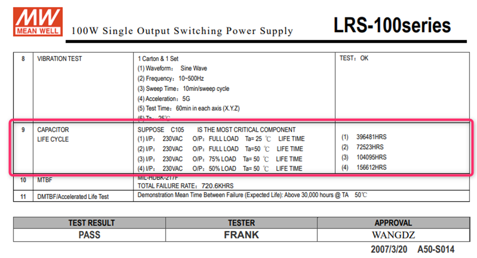
In the above example, if the power supply is used at 75dC at Ta 40dC, the estimated lifetime would be 2*104095 Hrs ~200K hrs.
In MEAN WELL’s specification you can find 2 derating curves, in below example the 300W open frame power supply: EPP-300
- The Derating Curve with the Ambient Temperature vs. Load
- The Derating Curve with the Input Voltage vs. Load

- In this Curve one can find that the maximum load of this power supply is 300W at 50dC when an external air flow of 20.5CFM is applied. For temperatures exceeding 50dC, 60dC for example additional derating need to be applied, in above case at 60dC the maximum load would be 225W. (50dC 300W, 70dC 150W => from 50dC to 60dC: 75W derating)
- In case this power supply would be used at 90VAC input, a derating of 80% must be applied. So, in previous example with the 20.5CFM forced air the max load would be 240W. In case of an ambient temperature of 60dC and a 90VAC input the maximum rated power would be 225W * 0.8 = 180W with 20.5CFM forced air.
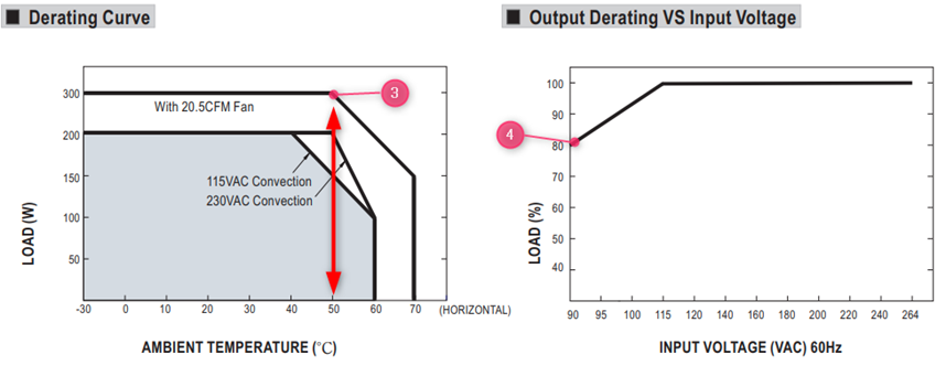
- If the power supply is used in an application without additional forced Air, the power supply will be derated to 200W till a maximum temperature of 50dC
- In case it will be powered by a 90VAC input the power supply has to be additionally derated to 80% of the 200W = 160W max
MTBF (Mean Time Between Failure) and Life Cycle are both indicators of reliability. MTBF can be calculated by two different methodologies, which are “part count” and “stress analysis”. The regulations, MIL-HDBK-217F Notice 2 and TELCORDIA SR/TR-332(Bellcore) are commonly used to calculate MTBF. MIL-HDBK-217F is a United States military standard, and TELCORDIA SR/TR-332(Bellcore) is a commercial regulation. MEAN WELL utilize MIL-HDBK-217F(Stress Analysis) as the core of MTBF. The exact meaning of MTBF is, after continuously using the power supply for a certain amount of time, the average time that the probability of proper operation is down to 36.8%(e-1=0.368). Currently MEAN WELL is adopting MIL-HDBK-217F, to predict the expected reliability through Stress Analysis (excluding fans); this MTBF means the probability of the product can continue the normal work after working continuously up to the calculated MTBF time is 36.8% (e-1=0.368). If the power supply is continuously used at double the MTBF time, the probability of proper operation becomes 13.5%(e-2=0.135.
DMTBF (Demonstrated Mean Time Between Failures) is a way of evaluating MTBF in a relatively short period of time based on accelerated deterioration (high stress, high temperature) tests under specific parameters and conditions. Please refer to the following equation for MTBF calculation.
This method compares to the previous methods, this calculation uses real test data to demonstrate the reliability of the power supply.
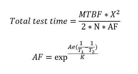
Where
MTBF: Mean Time Between Failure
- X2:Can be found in chi-square distribution
- N:Number of sampling
- AF:Acceleration factor, which can be derived from acceleration factor equation.
- Ae=0.6
- K(Boltzmann Constant)=(eV/k)
- T1:Rated temperature of specification. Note: Kelvin will be the unit use for calculation
- T2:The temperature that is used in the meaning of acceleration, and the chosen temperature could not result in physical change in materials.
Note: Kelvin will be the unit use for calculation.
Life Cycle (Capacitor Life Cycle) is found by using the temperature rise of electrolytic capacitors under maximum operating temperature to estimate the approximate life of the power supply. For example, RSP-750-12 MTBF=109.1K hours(25°C); electrolytic capacitor C110 Life Cycle=213K hours (Ta=50℃).
MEAN WELL considers the capacitor lifecycle calculation as the most important indicator for the estimated lifetime. The (D)MTBF is the main indicator for the reliability of the power supply. For more information please see: Investigation of The Lifetime & Reliability of Power Supply -MEAN WELL EUROPE Switching Power Supply
MEAN WELL’s safety reports, IEC reports and CB reports are not available online. In case you need these reports to validate your design with your certifying body, please contact your local MEAN WELL sales channel for support. If you are unable to get the support, please contact us via this website.
MEAN WELL’s User Manual can be found on www.meanwell.com
1. Go to products
2. Click on Installation Manual
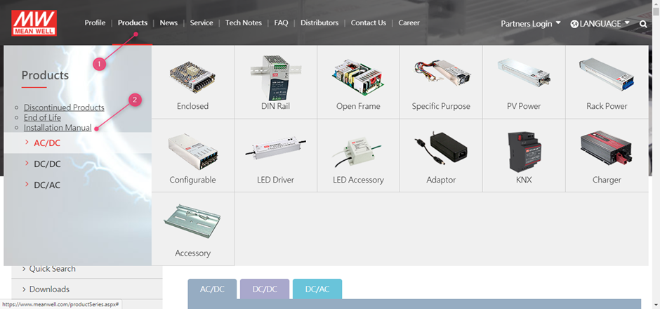
3. Scroll down to find the user manuals for the different product families.

MEAN WELL’s Safety certifications can be found on www.meanwell.com
- Use the search function on the website
- Fill in the series number in the search field (do not include the last extentions suchs as -12 in XLG-150-12
- Click the search button

4. Click on the PDF Link
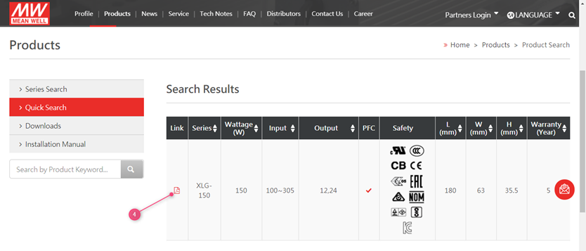
5. Click on the top on the certificate
6. All available certificates are shown and will show up once clicked upon
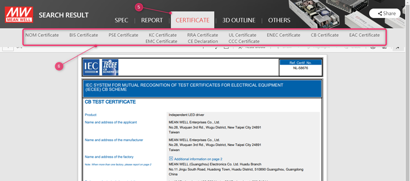
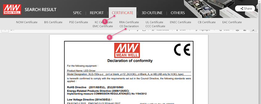
MEAN WELL’s CE declarations can be found on www.meanwell.com
- Use the search function on the website
- Fill in the series number in the search field ( do not include the last extentions suchs as -12
- Click the search button

4. Click on the PDF Link

5. Click on the top on certificate
6. Click on CE declaration
Select (1) Products followed by (2) downloads
MEAN WELL’s EMI test guide can be found on www.meanwell.com
Select (1) Products followed by (2) Downloads

After this scroll down to find the EMI testing of Power guide
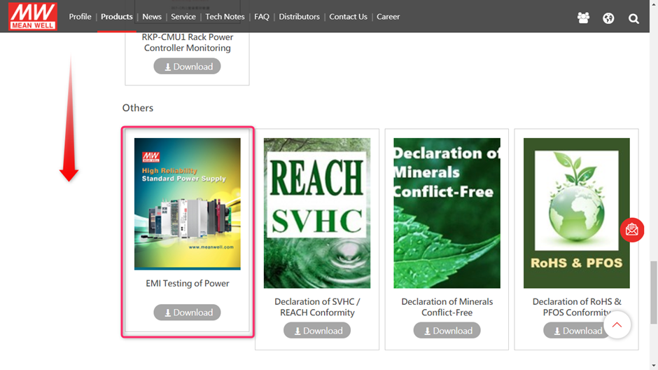
Or you can use this link to directly download the EMI testing guide:
EMI_statement_en.pdf
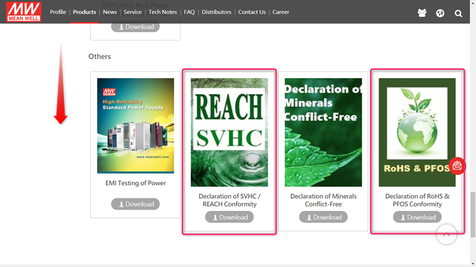
MEAN WELL’s RoHS and Reach statements can be found on www.meanwell.com
Select (1) Products followed by (2) Downloads:
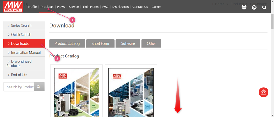
After this scroll down to find the RoHS declaration and Declaration of SVHC/ REACH conformity:
Or you can use the below links to download the declarations:
MEAN WELL’s Declaration of Conflict Free Minerals can be found on www.meanwell.com
Select (1) Products followed by (2) Downloads

After this scroll down to find the Declaration of Minerals Conflict Free
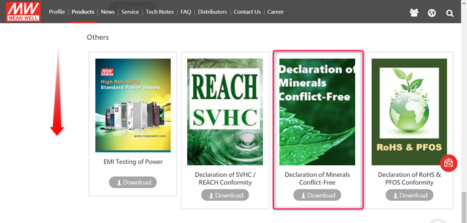
Or you can use this Link to directly download the EMI testing guide: