BATTERY: INDUSTRIAL CHARGER & PROGRAMMABLE POWER SOURCE
With the democratization of mobile devices, the drop of manufacturing cost of batteries, as well as the growing awareness on environmental topics issues, the technology of batteries and chargers has witnessed a tremendous breakthrough in the past few decades; numerous of new batteries have seen the light of day, and innovative charger applications are born as accompaniment.
From Electric Vehicle Charging (EV Charging) infrastructure to Energy Storage System (ESS), the modern chargers are utilized in numerous different sectors nowadays and are pushing the society further towards the more sustainable and renewable energy options.
MEAN WELL INDUSTRIAL CHARGERS
MEAN WELL is the global leading manufacturer of standard Power Supplies in the market. With over 40 years of experience in the development and production of Power Supplies, MEAN WELL offers a complete range of charging solutions to diverse fields, including the household, commercial and public sectors.
HOW CHARGER IS DIFFERENT FROM REGULAR POWER SOURCE
While common Power Supplies are designed to provide a fixed and constant DC voltage, chargers require a more complex design with different charging phases to assure the longevity of batteries and safety during operation.
To meet the specific charging needs of different types of batteries, industrial chargers are generally designed with several charging phases, including principally a boost voltage-constant current phase, a constant voltage phase, and a float voltage phase.
More advanced industrial chargers use a microcontroller (MCU) design, which detects the charging status of the connected batteries and allows further adjustment between different charging phases.
Nevertheless, it does not mean that chargers are the only option for charging applications nowadays. Advanced technology in power supplies has made it possible to adapt a programmable power supply, with adjustable voltage and current, to the specific charging demands in the field too.
HOW TO CHOOSE YOUR CHARGER
Choosing the adequate DC power source for the battery is critical if one wishes to maintain the battery’s performance. In the following paragraphs, we will be listing down a few criteria which are considered essential when it comes to the selection of proper chargers for the system.
A. Battery Charging Profile
Each battery type has its own specific charging needs and requirements. These requirements are normally defined by the battery manufacturer and listed in their specification. Hence it is important to start by identifying the battery charging profile before further diving into choosing the suitable charger. For the 2 most popular battery types used, we listed 2 example charging curves below:
- Lead-Acid Battery requires chargers with minimum 3 charging stages.

Image 1: Three Stages for Lead-Acid Battery
- Lithium-based Battery requires generally chargers with 2 charging stages: first with constant current, followed by constant voltage.
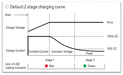
Image 2: Two stages for Lithium-based battery (LiFeP04, LiCoO2)
For more information read our “Lead-acid and lithium battery charging” article.
For more information about selecting the right charger for your battery please refer to our “Selecting a charger from your battery” article.
Tip: MEAN WELL offers a Smart Battery Charging Programmer (SBP-001) which allows users to configure via a user-friendly interface, the charging curve of selected MEAN WELL chargers and power supplies (e.g. Intelligent RCB-1600 charger, HEP-1000 for Harsh environment, ENC…etc.). With SBP-001 programmer, the user can set the output current and voltage to further simulate the charging curve for different batteries.
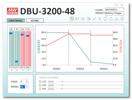
Image 3: Intelligent Charger DBU-3200, configurated via SBP-001 and its user-friendly interface (Click to download)
B. Regulations
According to International Electrotechnical Commission (IEC), numerous regulation standards exist for the purpose of ensuring safety, efficiency, reliability, and interoperability of electrical, electronic, and information technologies; depending on the application of the end device, the mandatory regulations can differ from one to another.
For instance, IEC/EN 60335-1 is the basic requirement for Household appliances’ design, aiming to prevent foreseeable hazards ones could encounter when using the end device. Furthermore, IEC/EN 60335-2-29 defines the requirements in detail for battery chargers intended for household battery charging.
Specific charger applications such as AC EV Charger might require an additional power source to power the auxiliary and communication modules inside the such charger. For these kinds of applications, one has to evaluate on the system level if power supplies with more strict requirements are needed, such as the IEC/EN 61558-1 certification and compliance with OVC III (Overvoltage category III) protection level. Power Supplies with OVC III compliance can be integrated without adding an extra isolation transformer on the input side and gives your products the best out in terms of flexibility and costs in a minimized space. In addition, using such power supplies in AC Charters gives greater flexibility in terms of installation as these would allow the charger to be permanently connected to a distribution panel.
As for chargers intending to power up UPS systems and battery test systems, IEC/EN 62368-1 and IEC/EN 62477 are generally the safety regulations to comply with.
In addition, the standards related to electromagnetic compatibility (EMC) emission and immunity are equally important to take into consideration. In case the charging system is certified according to the IEC/EN 62368-1; the EN 55032 and CISPR 32 standards must be confirmed; in case the system needs to be certified for the IEC/EN 60335-1, the emissions and immunity according to the EN 55014 have to be met. Other major EMC regulations which must be complied with are the IEC/EN 61000-3 and IEC/EN 61000-4.
Therefore, clarifying the specific requirements for safety and EMC regulation standards will greatly facilitate the selection of the battery charger process.
| Safety Regulation No. | MEAN WELL Series |
| EN62368-1 | HDR-15/30/60/100/150 ENC-120/180/240/360 NPB-120/240/360/450/750/1200/1700 RPB-1600 / RCB-1600 / DBR-3200/ DBU-3200 HEP-600C CSP-3000 PHP-3500 RST-10000/ 5000 BIC-2200 TDR-240/480/960 WDR-60/120/240/480 Adapter Charger: GC30/120/160/220/330 |
| OVC III (based on EN61558) | HDR-15/30/60/100/150 *PHP-3500 |
| OVC III (based on EN62368) | IRM-30/45/60/90 |
| EN60335-2-29 / EN60335-1 | NPB-120/240/360/450/750/1200/1700 |
| EN60335-1 | IRM-60/*90 *PHP-3500 |
*=Regulation Designed Ready, NRE needed by users request
C. Installation
The working environment and condition are essential to the reliability and lifetime of both battery and charger; engineers must take into consideration the eventual working and storage condition of the battery charger to further choose an adequate model for the design.
For instance, chargers designed as 5G vibration-proof are more suitable for installation located in a mobile device. E.g., wheelchair, E-bike, mobile working station, camper van…etc. Whereas waterproof and dust-resistant IP67 chargers and power supplies are generally recommended for application under humid and dusty environment, both indoor and outdoor.
On the other hand, it is not to forget that the working temperature is equally important to the longevity of battery charger and battery as the other working conditions mentioned earlier. Therefore, one should think about selecting a power source with adequate thermal dissipation design (e.g., convention cooling, forced air flow, conducted colling, water cooling…etc..) for the system too.
Last but not least, the selection of battery charger is sometime limited by the available space or specific installation method too; a 19-inch rack cabinet will probably need an 1U Battery Charger (e.g., 1U-tall RCB-1600) to save space and a DIN Rail cabinet will most likely adapt a DIN RAIL power source (e.g., HDR series with OVC III protection)…etc.
Future postings and articles:
In the upcoming future, MEAN WELL will also share its knowledge regarding the booming Energy Storage System (ESS) field. For instance, how to use MEAN WELL Chargers (programmable 67~400VDC) in a High Voltage Direct Current (HVDC) application, as well as the know-how on digital communication protocols (e.g., PMbus and CANbus), which can further perform voltage and current control for the Energy sector.
LEARN MORE ABOUT CHARGING POWER SUPPLIES
Explore our blog for insightful technical notes about Charging Applications.
Got questions?
Look at the section below to find the most frequently asked questions (with answers)
we received in Charging Applications.
Internally, IRM series has the following AC fuses, which are implemented on AC/L input:
| IRM-01/02/03 | T1A/L300V |
| IRM-05/10/15/20/30 | T2A/L300V |
| IRM-45/60 | T2.5A/L300V |
| IRM-90 | T3.15A/L300V |
Depending on the installation environment, you may need IP certified power supplies (IP65/IP67).
Also, waterproof connectors and junction boxes are useful accessories to ensure a reliable operation in damp environments (please refer to the LED power supply installation manual).
Waterproof connector solution
Junction box option
Note that the MEAN WELL product IP level, including IP67, is tested according to IEC 60529. The protection does not guarantee for permanently immersing in the water. Please check the device installation manual for proper suggestions on installation.
Capacitive loads can be found under many different forms: capacitor banks, batteries, and even power supplies themselves are considered as capacitive loads. The principal issue that can appear on such type of load is at PSU start-up: a discharged capacitor basically acts like a short-circuit at start-up, hence it may overload the output.
One solution is either to add current limiting resistors in series with the capacitive load to limit the output current, or to select a power supply with “constant current limiting” overload protection type. This way, the power supply will automatically limit the current to a certain level stated in the specifications:

SPV-150 series specifications
For inductive loads, motors need high current at start-up, therefore a power supply with peak power capability is recommended (or a PSU with constant current limiting overload protection type).
The main issue of dynamic loads is output voltage drop. If the load step is too high in amplitude and too long, it may be able to completely discharge the output capacitors and then create a voltage drop or high ripple at the output. If the frequency of the load changes is high enough, this kind of issue is less likely to happen (please refer to the test reports for more information). One solution could be to put additional capacitors between Power Supply and load.
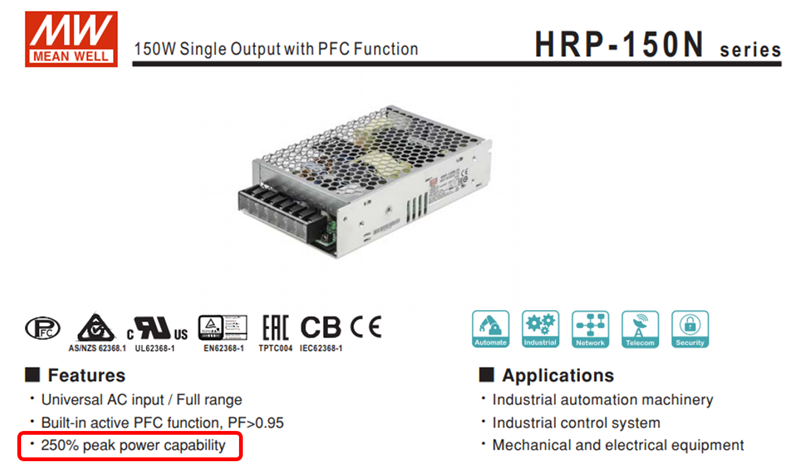
Some applications may need to draw short peak currents from the power supply. If the PSU overload protection type is hiccup or constant current limiting mode, then it will not be able to provide the current peak needed by the load. Some of our power supplies come with a peak power capability that makes them suitable for these kinds of applications. (e.g. HRP-150N series)
For open-frame power supplies with peak capability, the user should refer to the derating curves, and check the thermal requirements (a fan may be required).
A TTL signal, Transistor-Transistor-Logic, is a binary signal generated with the help of a transistor turning on or off. 0-0.4V is considered as low state, and 2.7-5V is a high state.
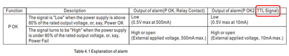
The difference between the TTL and Relay Contact topologies is that since in Mean Well products the TTL signal is created through a transistor or semiconductor, the current capability of the signal is relatively low. In contrary, using Relay Contact method (which uses a metal contact as conductor) allows much higher current to flow.

Generally, at no load or light load, the power factor is relatively low. In such conditions, although the active power is low, the reactive power and input current is quite high, which results in high measured current using a multimeter. In order to accurately measure the active power, the RMS input current, RMS input voltage, as well as the distrotion and phase shift between V and I curves should be measured (with a powermeter, or an oscilloscope).
If only measuring V and I RMS values, the result is the apparent power, which comprises real and reactive power.
Some models may require to use the Remote Off function to achieve low no load power consumption.
MEAN WELL developed many power supplies series specifically for LED application. Single stage PFC was used in such developments due to low cost. This topology has the following restrictions:
AC fluctuation
- This topology does not use input bulk capacitor. For this reason, in areas with low AC quality, output voltage and current may become unstable causing variation in LED brightness. If the input AC voltage is stable, then this problem will not occur.
- Output ripple
This is also caused by lack of input bulk capacitor. As compared to power supplies using two-stage PFC, the ripple will be significantly larger (see Figure 4). There could be instances where the low end of the ripple may be too low for the driver IC to operate properly, and the LEDs will start to flicker. To solve this type of problem, the output voltage can be adjusted higher, so the low end is higher than the driver’s minimum working voltage. Or simply select a PSU with higher rated voltage.
- Current harmonics
Single stage PFC power supplies are optimized for constant current drive. Using these supplies as constant voltage sources (such as application including cascading a constant current driver IC), the harmonics might be worsening in this case. When operating in areas with unstable utility voltage or with driver IC, we highly recommend using general application types as found in table 1. Avoid using single stage PFC if possible and use a two-stage PFC power supply instead, or contact MEANWELL for more information.

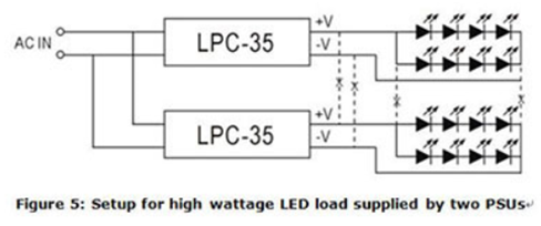
MEAN WELL LED power supply does not have a parallel “current sharing” function, so it is not suitable for parallel connection. For high power requirements, please select higher wattage power supply or divide LED load into smaller subsections to be powered by individual power supplies. Example of such LED configuration can be found in figure 5. As shown in fig. 5, the connection between -V of the LPC-35 units should be severed and not connected in common. On the contrary, small wattage LED loads can be connected in parallel and be powered by a single high wattage power supply. But the ability to divide current evenly must be taken into consideration.
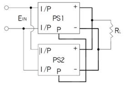
When power supplies are connected in parallel, mostly, is intended to increase the output current. Due to the design of active current sharing, they are mostly without reverse current protection, therefore, they are not the best solution when talking about redundancy. For redundant purposes, please choose the PSU with redundant function or implement external redundant modules. Be sure that the difference in output voltage and wiring impedance, should be as small as possible.
1. Use PSP models as an example, connect P(LP/CS) terminals together (Please refer to the parallel function in the specification). Input and output should be connected in parallel before connecting to the AC source and loads. Shown as in the picture below (some specific power supplies require a minimum load after paralleling).
2. Output voltage difference between power supply units should be as small as possible, normally < 0.2V.
3. The power supplies should be paralleled with short and large diameter wiring together first, and then connected to the load.
4. After paralleling, the maximum usage of total power should be around 90% of the rated total power.
5. When the power supplies are paralleled, if the load is lower than 10% of the rated load of the individual power supply, the LED indicator or signals (Power Good, Pok, Alarm Signal) may malfunction.
6. To ensure that the load current is effectively shared in parallel operation, in general, it is recommended not to use more than 4-6 power supplies at one time. Please follow the maximum number of units as stated in the datasheet.
7. In some models, the +S, -S terminals should be used to reduce unstable pulsation of output voltage.
COM (COMMON) means common ground. Please see below:
Single output: Positive pole (+V), Negative pole (-V)Multiple outputs (Common ground): Positive pole (+V1, +V2,.), Negative pole (COM)
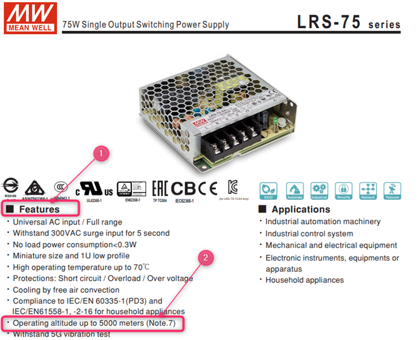
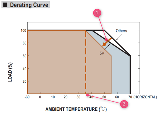
Yes, for power supplies certified >2000m please read the “note” in the spec.
In general, for unpotted models, a derating of 5°C/1000m has to be applied and for potted models, a derating of 3.5°C/1000m has to be applied.
For example LRS-75-24:
The datasheet shows:

The Note. 7 shows:

At 5000m the derating curve will need to move 15°C following the arrow (1)
At full load the maximum operating temperature at 5000m will be 35°C shown at (2)
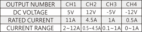
There are some minimum-load requirements on MEAN WELL’s multi-output power supplies. Please read the specification first before connecting to the load. To allow the power supply to work properly, a minimum load for each output is required, or else, the output voltage level will be unstable or outer tolerance range. Please refer to “Current range” in the specification as shown in the table below: Channel 1 requires a 2A minimum-load; channel 2 requires 0.5A; Channel 3 requires 0.1A ; Channel 4 does not need any minimum-load.
In general, there are two circumstances that will cause the power supply to shut down. The first one is the activation of the overload protection (OLP). To deal with this situation, we suggest increasing the rating of the output power or modifying the OLP point. The second one is the activation of over temperature protection (OTP) when the internal temperature reaches the pre-set value. All these conditions will let the Power Supply enter protection mode and shut down. After these conditions are removed, the Power Supply will be back to normal.
Cooling fans have a relatively shorter lifetime (typical MTTF, Mean Time To Failure, of around 5,000-100,000 hours) compared with other components of power supply. As a result, changing operating method of the fans can extend the operation hours. The most common control schemes are shown as below:nnTemperature control: if the internal temperature of a power supply, detected by a temperature sensor, is over the threshold, the fan will start working at full speed, whereas, if the internal temperature is less than the set threshold, the fan will stop working or run at half speed. In addition, cooling fans in some power supplies are controlled by a non-linear control method whereby fan speed can be changed with different internal temperatures synchronously.nLoad control: if the loading of a power supply is over the threshold, the fan will start working at full speed, whereas, if the loading is less than the set threshold, the fan will stop working or run at half speed.
At input side, there will be (1/2 ~1 cycle, ex. 1/120 ~ 1/60 seconds for 60 Hz AC source) large pulse current (Ipk 20~100A based on the design of power supply) at the moment of power-on and then back to normal rating. This “Inrush Current” will appear every time you turn on the power. Although it will not damage the power supply, we suggest not turning the power supply ON/OFF very quickly within a short time.

A more critical situation can occur if there are several power supplies turning on at the same time, the dispatching system of AC source may shut off and go into protection mode because of the huge inrush current. It is suggested that these power supplies start up one by one or use the remote control function of power supply to turn them on/off.
COM (COMMON) means common ground. Please see below:nSingle output: Positive pole (+V), Negative pole (-V)nMultiple output (Common ground): Positive pole (+V1, +V2,.), Negative pole (COM)
Due to different circuit designs, the MEAN WELL power supply’s input consists of three types as below:
(VAC≒VDC)
a. 85~264VAC;120~370VDC
b. 176~264VAC;250~370VDC
c. 85~132VAC/176~264VAC by Switch; 250~370VDC
- In a and b inputs models, power supply can work properly no matter under AC or DC input. Some models need correct connection of input poles, positive pole connects to AC/L; negative pole connects to AC/N. Others may require opposite connection, positive pole to AC/N; negative pole to AC/L. If customers make a wrong connection, the power supply will not be broken. You can just reverse the input poles and power supply will still work.
- In c input models, please make sure that you switch the 115/230V input correctly. If the switch is on the 115V side and the real input is 230V, the power supply will be damaged.
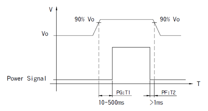
Some power supplies provide a “Power Good” signal when they are turned on and send out a ” Power Fail” signal when they are turned off. This is usually used for monitoring and controlling purposes.
- Power Good: after the output of a power supply reaches 90% rated voltage, a TTL signal (about 5V) will be sent out within the next 10-500ms.
- Power Fail: before the output of a power supply is less than 90% rated voltage, the power-good signal will be turned off at least 1ms in advance.
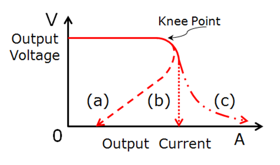
When current drawn exceeds the rating of the PSU, the protection circuit will be triggered to protect the unit against overload/overcurrent.
Protections of overload/overcurrent can be divided into several forms:
(1)FOLDBACK CURRENT LIMITING
Output current decreases about 20% of rated current, shown as curve (a) in the figure below.
(2)CONSTANT CURRENT LIMITING
Output current remains at a constant level and within the specified range while the output voltage drops to a lower level, shown as curve (b) in the figure below.
(3)OVER POWER LIMITING
Output power remains constant. As output load increases, output voltage decreases in proportion, shown as curve (c) in the figure below.
(4)HICCUP CURRENT LIMITING
Output voltage and current keep pulsing ON and OFF repeatedly when protection is activated. The unit automatically recovers when the faulty condition is removed.
(5)SHUT OFF
Output voltage and current are cut off when output load reaches protection range.
NOTE: Protection mode of some of the products combines with different types of the forms mentioned, such as constant current limiting + shut down.
Recover method:
(1)Auto Recovery: PSU recovers automatically after faulty condition is removed.
(2)Re-power on: PSU restarts by manual AC re-power on after faulty condition is removed.
Note: Please do not operate PSU in overcurrent or short-circuit condition for a long period of time to prevent a shorten lifespan or damaging the PSU.
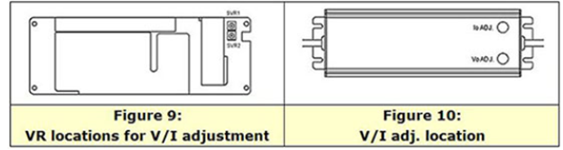
LED power supply comparison table to see which MW LED power supply allows for V/I adjustments. A suitable unit can be picked based on the type of adjustment required. For the allowed adjustment range, please refer to the spec sheet. Tuning of the voltage and current levels can be done through the built-in VRs/potentiometers. PLN/ELN requires removal of the top cover in order to access the internal SVR1 and SVR2, see figure 9 for VR locations. For other series, the VRs can be accessed through IoADJ and VoADJ holes after rubber stopper removal. After adjustments have been made, please make sure rate power is not exceeded and the rubber stoppers are properly reassembled.
With 1~10V dimming, the lighting unit can be dimmed down to 10%; with 0~10V dimming, it can be dim down to 0%, or say, dim-to-off.
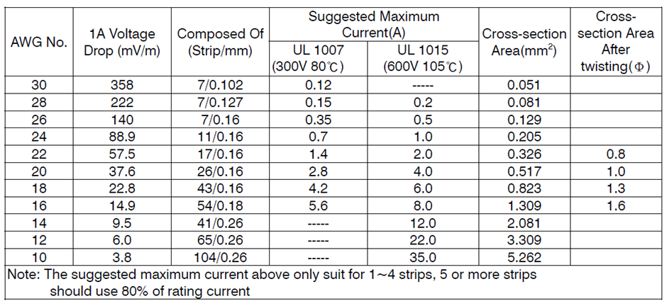
To install a power supply into the system, you would need wires for the connection both to the loads and to the energy source. There are a couple of points that should be taken into consideration when choosing wires, one is the current rating, it may cause high heat on the wires or burnt out in the worst case if the rating is not enough. The other is voltage drop, there would be voltage reduction at load side as current moves through the wires owing to the internal resistance. If too many voltage drop in a line, there could be no sufficient voltage to drive the loads. You can find the right wires for use by referring to the table below on the basis of your system design.
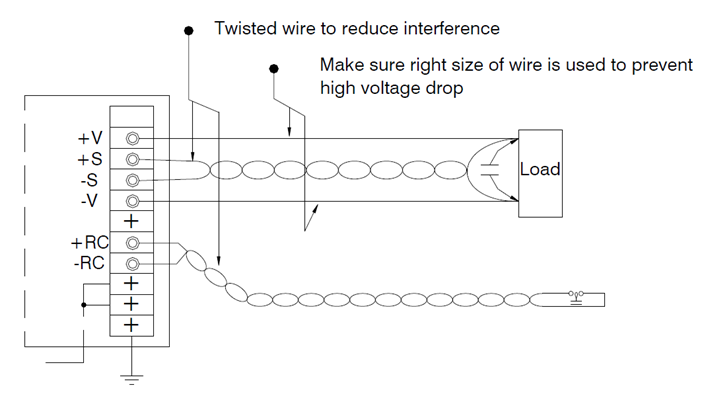
First, use twisted wires, connect +S to the positive end of the output, then -S to the negative end of the output, as shown in the illustration. Also, keep the wires off the AC and output cables to prevent noise interference.
Add capacitors at the output end where the Remote Sensing wires are connected to if the dynamic load (frequency above 1K Hz) is used. The purpose is to reduce noise as Remote Sensing is a sensitive function. A suitable capacitor requires two factors:
a. Rated Ripple Current is 0.2 times greater than the output current
b. Rated Voltage is higher than the output voltage
If you connect the power supply to motors, light bulbs, or high capacitive loads, you will have a high output surge current when you turn on the power supply and this high surge current will cause failure of startup. We suggest using power supply with constant current limiting protection to deal with these loads.
Yes. Since our products are designed based on isolation concept, it will be no problem that the output ground (GND) and frame ground (FG) is the same point in your system. But EMI may be affected by this connection.
Yes this is normal. Leakage current is the current flowing from the protective earth (PE) conductor, such as metal enclosure, of equipments to frame ground (FG). Due to EMI requirement for the power supply, there are Y capacitors connected in between AC L/N and PE conductor. A low current will flow through the Y-caps to FG. In reality, leakage current should be regulated to comply with safety standards. In regulations of safety for IT products, leakage current should be less than 3.5mA for portable Class I equipment, 0.75mA for hand-held Class I equipment, and 0.25mA for Class IInequipment.
Because of the low current flowing, this is not harmful for the human body. For medical power supplies there are however more strict regulations regarding leakage current.
For more information, please see our Medical Application page
Depending on the circuit design, there could be different operational problems. See below:
- Boost mode driver IC:
The startup voltage of such driver IC is significantly lower than the total LED forward voltage. For this reason, the IC will start up at very low voltage level usually about 1/2 of the power supply’s rated voltage and to meet rated power requirement, the startup current will reach 2 times the power supply’s rated current. When the power supply is unable to provide this current, the LED CC driver will not activate.
- Buck mode driver IC:
If the selected power supply voltage is significantly higher than the LED forward voltage. For example, power supply provides 48V and the LED lamp only needs 24V and the power ratings are equivalent. When power supply voltage reached the LED conduction voltage, the power supply will immediately go into constant current mode. At this moment, the required power to start up the LED + driver is larger than what the power supply can provide causing malfunction of the driver circuit and the power supply to be clamped at LED forward voltage. For boost mode design, we recommend raising the startup voltage of the driver IC to be as close to the power supply voltage as possible or incorporate soft start function (see fig. 3). Wait until the power supply voltage is established before starting the driver. When selecting power supply for buck mode, the output voltage of the power supply should be as close to the LED total voltage as possible with excess power available (LED power/0.85).
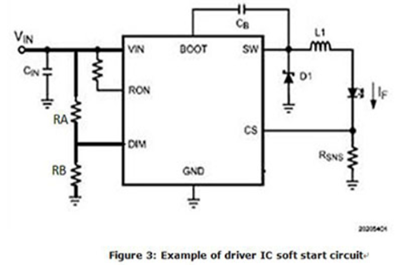
DIM PIN is the startup pin for most PWM based driver. It can also be designated as EN (Enable). DIM (or Enable) is at 0V the internal connection to SW pin will be open. When the DIM voltage reaches 1.5V (Typ), the IC will Turn ON. To set the Vstart for the DRIVER IC: Vstart = (VDIM/RB) x (RA+RB). The general rule is to set the Vstart at 5~10% higher than the total LED forward voltage.
LDD/LDH series comprises switching components; series or parallel connection will damage these switching components.
First of all. Determine the driving method of LED lamp. If the lamp is driven by constant current, forward current shall be within specification. On the contract, if it’s driven by constant voltage, then user must check if they are using the right product to dim the LED lamp, such as PWM/IDLV/ODLV series.
Yes in this situation the AUX power is available to be able to use the remote on/off function.
During safety verification process, the agency will use a stricter standard ±10% (IEC 62368 uses +10%, -10% for the product with AC input rated) of the input voltage range labeled on the power supply to conduct the test. So, operating at the wider input voltage range as specified on the spec. sheet should be fine. The narrower range of input voltage labeled on the power supply is to fulfill the test standard of safety regulation and make sure that users insert input voltage correctly.
If the two phases are 180o out of phase (split phase system), then yes. The resulting voltage will be around 240VAC, so it can be used with power supplies that has input range of 200VAC-240VAC.
If the two phases are 120o out of phase, the resulting RMS voltage will be 208VAC, so it should work, but derating might be needed on some models.
For a single-phase operation, you should check the input range of the power supply in its datasheet (derating might be necessary at low input voltage).
The hold-up time is the duration between the instant when the input is shut off, and when the output voltage falls below 90% of the rated output voltage. The hold-up time is highly dependent on the internal capacitances of the PSU and the load: the higher the capacitance, the longer the hold-up time and the higher the load, the shorter the hold-up time. nA common way to increase this parameter is to use buffer modules, such as our DBUF series, or if the hold-up time only needs to be slightly increased, you could use a Power Supply with a higher power rating. (The hold-up time on the specification is based on full load condition)
PMBus full name is Power Management Bus is an open standard for digital power management. The physical layer is based on I2C, and PM Bus had a set of commands that specifically design for power supply industry. More information can be found in https://pmbus.org/
MEAN WELL Rack Power and intelligent power supply and chargers have optional PMBus solution for example: PHP-3500 and HEP-1000 further the RCP/RSP-1600, UHP-2500 and DPU-3200 have this optional available.
A Controller Area Network (CAN Bus) is a bus standard initially developed for vehicle designed to allow multi-master with priority control without a host computer. The latest version is CAN 2.0 which consists of part A and part B. CAN 2.0A is for standard format with 11-bit identifier, and CAN 2.0B is for extended format with 20-bit identifier. CAN Bus is widely used in Automotive and industrial automation. There are not only 1 but many higher layer protocol such as CANopen, DeviceNet and more.
MEAN WELL CAN Bus product support CAN 2.0B (ISO-11898) with baud rate 250Kbps
MEAN WELL offers optionally CAN bus for PHP-3500, HEP-1000, RCP/RSP-1600, UHP-2500 and DRP/DPU-3200 and DBR/DBU-3200.
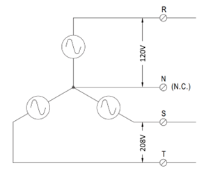
For a 3 phase PSU, the input port L1 L2 L3 and FG should be connected to AC phase R, S, T and PE respectively. In some cases, neutral might be needed and can be configured as below:
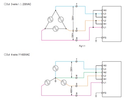
The same configuration can also be used if one want to use multiple single phase power supply for three phase connection.
For specific power supplies i.e., 3 phase power supplies with a lower power, a dual phase operation is possible by directly connecting the 2 phases to two of the three input ports of the power supply.
DC input can also be used by applying the positive wire to any of the input ports, and the negative one to another. In both cases, derating may be needed. (e.g., TDR series)

Most MEAN WELL power supplies are certified to be operated till 2000m. For some models the certification is valid for a higher altitude, this will be shown on the first page of the power supply under features (1)(2).
Please note that derating is needed at an altitude above 2000m. See FAQ “Do I need to derate my power supply when I used it over 2000m?”