In the section below, you can find the most frequently asked questions (and answers) we received.
These are categorized in Operation, Reliability, Compliance, and Others.
You can select the FAQs by category or use the search function at the top of the website to directly search for information.
If you cannot find the information you are looking for, use the “DON’T FIND ANSWERS? CONTACT US” button on the top right side of our website.
MEAN WELL’s specification shows the absolute values which were verified during design quality verification tests. Those condition are guaranteed by manufacture from quality and warranty perspectives.
When certifying a power supply according to a certain norm, there is normally a requirement described in this standard a certain tolerance which must be considered. (See also FAQ: Why Is The Input Voltage On The Label Different From The Input Voltage In The Spec? For Example, The Specification Shows Is 88~264 VAC While The Label On The Power Supply Says That It Is 100~240VAC?)
The specification shows what is possible, the report and label of the power supply shows what is approved by the certifying body according to the standards.
Besides the difference due to tolerance there might also be another reason why the specification and label/test report show a different temperature. For example, if the power supply needs to be derated at a low voltage input such as 100VAC, the label and test report might show the max temperature at full load based on this low input.
Different standards might have different tolerance requirements and different ranges this could mean that the most conservative value, or multiple values will show up on the label of the power supply.
In general MEAN WELL’s power supplies with a fan will continue to spin in no load condition. For certain power supplies where the fan will turn off in no load condition this will be marked (1) in the feature section of the specification:

MEAN WELL has incorporated dust proofing and waterproofing into the majority of its LED power supply design. Mainly based on the international standard IEC60529, detailed descriptions can be found in the following table:
(Note: PSUs with IP64 rating or above are suitable for indoor or outdoor applications in sheltered locations)
IP xy protection level
| Degree of protection, foreign bodies (x) | Degree of protection, moisture(y) |
| 0. Not protected 1. Solid foreign object (>50mm) 2. Solid foreign object (>12mm) 3. Solid foreign object (>2.5mm) 4. Solid foreign objects of 1,0mm diameter and greater 5. Amount of dust that would interfere with normal operation Dust tight | 0. Not protected 1. Vertically falling water drop 2. Vertically falling water drop when enclosure is tilted up to 15 degrees 3. Water sprayed at an angle up to 60o on either side of the vertical 4. Water splashed against the component from any direction 5. Water projected in jets from any direction (12.5 liter/minute) 6. Water projected in powerfil jets from any direction (100 liter/minute) 7. Temporary immersion in water ( 1 meeter from the surface of the water for 30 minutes) 8. Continuous immersion in water, or as specified by the user / manufacture |
*IP64-IP66 level products are suitable for damp indoor or sheltered outdoor environment. For actual installation limitations, please refer to the corresponding IP level tests.
*All products cannot be continuously submerged in water.
*The definition of IP68 by MEAN WELL: Immerse a unit under test in 1 meter below the surface of the water, tested with a dynamic condition where 12-hour AC on; 12-hour AC off.
Test duration: 1 month.
Nowadays, customer implement magnetic component in their system to achieve fast installation and maintenance. The magnetic component should keep as far as possible from PSU to avoid interference in the control circuitry of PSU. If limitation of distance is unavoidable, install a well magnetic-conducted metal plate (ex: steel plate, copper plate) between PSU and magnetic component to minimize the interference.
MEAN WELL’s component self-heating can be found on www.meanwell.com
1. Use the search function on the website to find the right product
2. Fill in the series number in the search field (do not include the last extensions such as -12 in XLG-150-12)
3. Click the search button
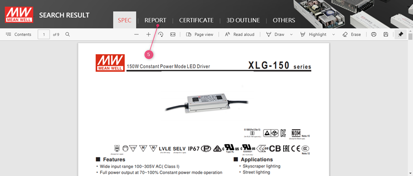
4. Click on the PDF icon to open the specification

5. Click on report

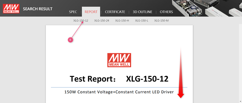
6. Click on the model and scroll down:

7. The temperature of the critical component can be found in the chapter Reliability Test under item 1 Temperature Rise Test
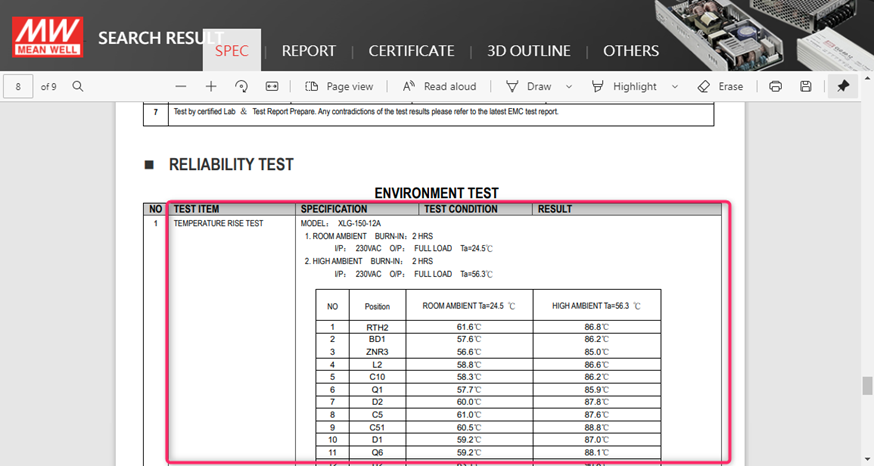
For more details about the component type for each position, please use the Contact Us function on this website.
MEAN WELL’s DMTBF can be found on www.meanwell.com
Please note that the DMTBF is not for every model available. Mostly this information is available for the LED drivers and our latest product releases.
1. Use the search function on the website to find the right product
2. Fill in the series number in the search field (do not include the last extensions such as -12 in XLG-150-12)
3. Click the search button
4. Click on the PDF icon to open the specification

5. Click on report
6. Click on the model and scroll down:
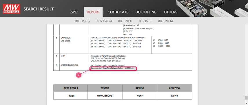
7. The DMTBF is shown on the last page of the report in the chapter Reliability test
MEAN WELL’s MTBF can be found on www.meanwell.com
1. Use the search function on the website to find the right product
2. Fill in the series number in the search field (do not include the last 3. extensions such as -12 in XLG-150-12)
3. Click the search button
4. Click on the PDF icon to open the specification
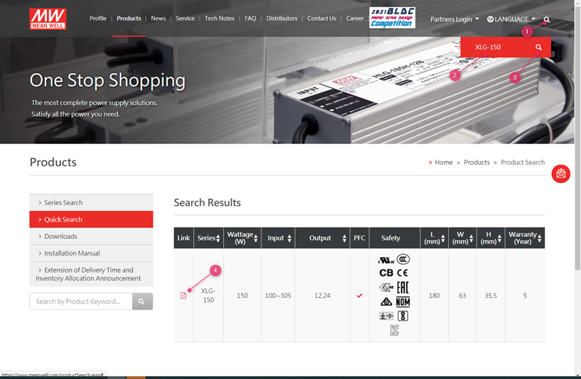
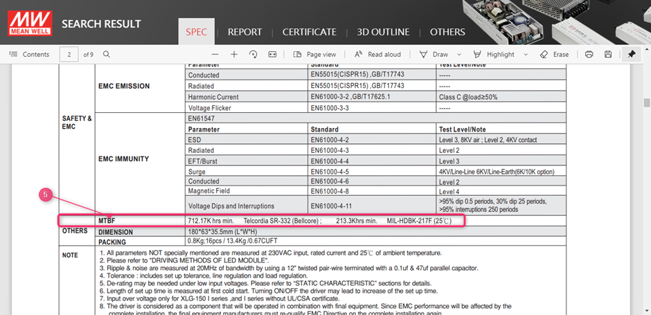
Scroll down in the specification to the bottom of the second page
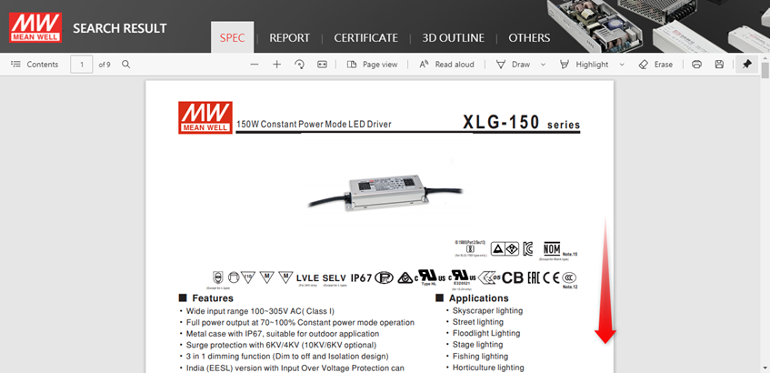
5. Find the MTBF value in under others:
MEAN WELL’s capacitor lifecycle calculation can be found on www.meanwell.com
1. Use the search function on the website to find the right product
2. Fill in the series number in the search field (do not include the last extensions such as -12 in XLG-150-12)
3. Click the search button
4. Click on the PDF icon to open the specification

5. Click on report

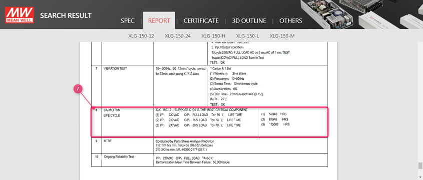
6. Click on the model and scroll down:

7. The Capacitor life cycle calculation is shown on the last page of the report in the chapter Reliability test
The Capacitor life cycle calculation is considered as the key indicator for the lifetime of the power supply. Please refer to the test report of the power supply on www.meanwell.com for the capacitor life cycle calculation.
As a rule of thumb, every 10dC increase the lifetime will be cut in half and vice versa for every 10dC decrease in temperature.
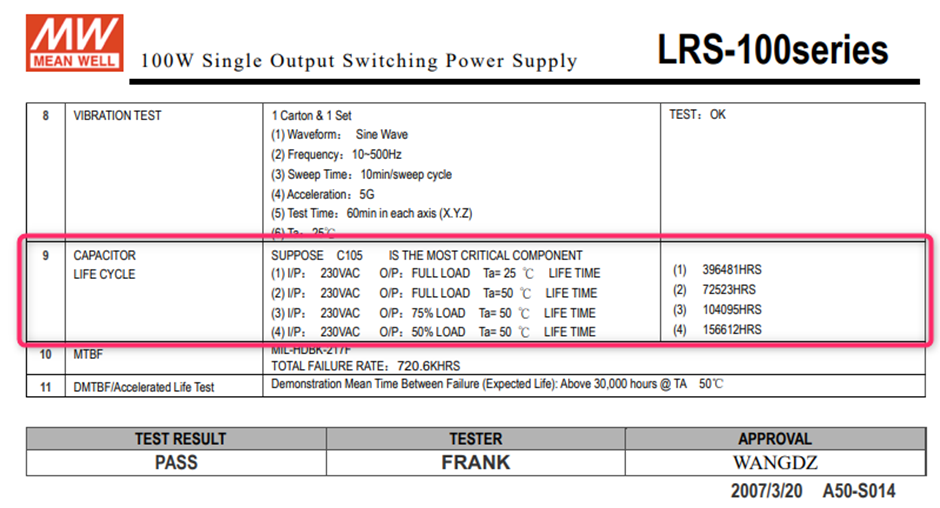
In the above example, if the power supply is used at 75dC at Ta 40dC, the estimated lifetime would be 2*104095 Hrs ~200K hrs.
This depends on the condition the power supply is used in. Please contact us for specific situations.
In general, the possibility to use the power supply in a higher temperature than specified is very low and all certifications of the power supply will become invalid.
MEAN WELL offers a selection of Surge Protection Devices to protect the power supply against surges and voltage peaks.
- Select products
- Type in “SPD” in the search field
- You will find several available SPD’s
Most small wattage and fanless power supplies are mainly installed in the horizontal position. If you have to install it vertically because of mechanical limitation, you should consider the output derating due to the heat concern. The temperature derating curve can be found on the spec sheet. Regarding the power supplies with built-in fan or the application has forced cooling system, vertical and horizontal installations have less difference. Ex. In SP-150 derating curve, the ambient temperature difference in application is 5 Celsius from vertical to horizontal. The output wattage in forced cooling can be 20% higher than air cooling convection.
Depending on the cooling mechanism of the power supply there are different considerations and restriction towards the mounting orientation of the power supply and distance towards other components and self-heating components.
In general, please check our power supply user manuals on www.meanwell.com (Installation Manual-MEAN WELL Switching Power Supply Manufacturer). The actual distance and orientation depend normally on system design. Customers must review and test the power supplies in the real application and environment.
General guidelines for power supplies with different cooling mechanisms:
- Power supplies with an internal fan or which are cooled with an external fan have less constraints regarding the orientation in which they are mounted. Nevertheless, the fans and ventilation holes must be kept free from any obstructions. Also, a 10-15 cm clearance must be kept from any adjacent heat source
- A convection cooled power supply with standard a vertical mounting orientation which will be mounted in another orientation have to be derated by 5dC. See FAQ What should be noticed when installing a power supply in vertical and horizontal directions? Additionally ventilation holes must be kept free from any obstructions. Also, a 10-15 cm clearance must be kept from any adjacent heat source
- Din rail power supplies can only be mounted in the specified orientation. This is with the ventilation holes at the bottom and on top of the power supply. No other mounting directions are recommended. Allow good ventilation clearances, 5mm left and right, 40mm above and 20mm below, around the unit in use to prevent it from overheating. Also, a 10-15 cm clearance must be kept when the adjacent device is a heat source.
- For conduction cooling power supplies, the temperature on the Tc point is the key indicator if a mounting position can be allowed. The Tc position (1) and max Tc temperature (2) can be found in the product specification. Conduction cooled power supplies are for example IP65~IP68 LED drivers and base plate cooled power supplies such as UHP)

In MEAN WELL’s specification you can find 2 derating curves, in below example the 300W open frame power supply: EPP-300
- The Derating Curve with the Ambient Temperature vs. Load
- The Derating Curve with the Input Voltage vs. Load

- In this Curve one can find that the maximum load of this power supply is 300W at 50dC when an external air flow of 20.5CFM is applied. For temperatures exceeding 50dC, 60dC for example additional derating need to be applied, in above case at 60dC the maximum load would be 225W. (50dC 300W, 70dC 150W => from 50dC to 60dC: 75W derating)
- In case this power supply would be used at 90VAC input, a derating of 80% must be applied. So, in previous example with the 20.5CFM forced air the max load would be 240W. In case of an ambient temperature of 60dC and a 90VAC input the maximum rated power would be 225W * 0.8 = 180W with 20.5CFM forced air.
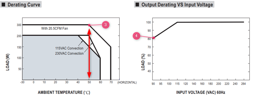
- If the power supply is used in an application without additional forced Air, the power supply will be derated to 200W till a maximum temperature of 50dC
- In case it will be powered by a 90VAC input the power supply has to be additionally derated to 80% of the 200W = 160W max
LED Drivers are recommended operate at full load as long as it observes the working temperature specified in the datasheet, which means Tc measurement results should be equal to or less than the stated Tc in the datasheet. 5 years warranty complies as long as drivers operate within working Temperature and Tc. Limit as well.
MTBF (Mean Time Between Failure) and Life Cycle are both indicators of reliability. MTBF can be calculated by two different methodologies, which are “part count” and “stress analysis”. The regulations, MIL-HDBK-217F Notice 2 and TELCORDIA SR/TR-332(Bellcore) are commonly used to calculate MTBF. MIL-HDBK-217F is a United States military standard, and TELCORDIA SR/TR-332(Bellcore) is a commercial regulation. MEAN WELL utilize MIL-HDBK-217F(Stress Analysis) as the core of MTBF. The exact meaning of MTBF is, after continuously using the power supply for a certain amount of time, the average time that the probability of proper operation is down to 36.8%(e-1=0.368). Currently MEAN WELL is adopting MIL-HDBK-217F, to predict the expected reliability through Stress Analysis (excluding fans); this MTBF means the probability of the product can continue the normal work after working continuously up to the calculated MTBF time is 36.8% (e-1=0.368). If the power supply is continuously used at double the MTBF time, the probability of proper operation becomes 13.5%(e-2=0.135.
DMTBF (Demonstrated Mean Time Between Failures) is a way of evaluating MTBF in a relatively short period of time based on accelerated deterioration (high stress, high temperature) tests under specific parameters and conditions. Please refer to the following equation for MTBF calculation.
This method compares to the previous methods, this calculation uses real test data to demonstrate the reliability of the power supply.
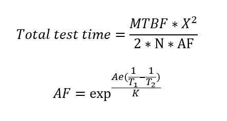
Where
MTBF: Mean Time Between Failure
- X2:Can be found in chi-square distribution
- N:Number of sampling
- AF:Acceleration factor, which can be derived from acceleration factor equation.
- Ae=0.6
- K(Boltzmann Constant)=(eV/k)
- T1:Rated temperature of specification. Note: Kelvin will be the unit use for calculation
- T2:The temperature that is used in the meaning of acceleration, and the chosen temperature could not result in physical change in materials.
Note: Kelvin will be the unit use for calculation.
Life Cycle (Capacitor Life Cycle) is found by using the temperature rise of electrolytic capacitors under maximum operating temperature to estimate the approximate life of the power supply. For example, RSP-750-12 MTBF=109.1K hours(25°C); electrolytic capacitor C110 Life Cycle=213K hours (Ta=50℃).
MEAN WELL considers the capacitor lifecycle calculation as the most important indicator for the estimated lifetime. The (D)MTBF is the main indicator for the reliability of the power supply. For more information please see: Investigation of The Lifetime & Reliability of Power Supply -MEAN WELL EUROPE Switching Power Supply
MEAN WELL’s specification shows the absolute values which were verified during design quality verification tests. Those condition are guaranteed by manufacture from quality and warranty perspectives.
When certifying a power supply according to a certain norm, there is normally a requirement described in this standard a certain tolerance which must be considered. (See also FAQ: Why Is The Input Voltage On The Label Different From The Input Voltage In The Spec? For Example, The Specification Shows Is 88~264 VAC While The Label On The Power Supply Says That It Is 100~240VAC?)
The specification shows what is possible, the report and label of the power supply shows what is approved by the certifying body according to the standards.
Besides the difference due to tolerance there might also be another reason why the specification and label/test report show a different temperature. For example, if the power supply needs to be derated at a low voltage input such as 100VAC, the label and test report might show the max temperature at full load based on this low input.
Different standards might have different tolerance requirements and different ranges this could mean that the most conservative value, or multiple values will show up on the label of the power supply.
In general MEAN WELL’s power supplies with a fan will continue to spin in no load condition. For certain power supplies where the fan will turn off in no load condition this will be marked (1) in the feature section of the specification:
MEAN WELL has incorporated dust proofing and waterproofing into the majority of its LED power supply design. Mainly based on the international standard IEC60529, detailed descriptions can be found in the following table:
(Note: PSUs with IP64 rating or above are suitable for indoor or outdoor applications in sheltered locations)
IP xy protection level
| Degree of protection, foreign bodies (x) | Degree of protection, moisture(y) |
| 0. Not protected 1. Solid foreign object (>50mm) 2. Solid foreign object (>12mm) 3. Solid foreign object (>2.5mm) 4. Solid foreign objects of 1,0mm diameter and greater 5. Amount of dust that would interfere with normal operation Dust tight | 0. Not protected 1. Vertically falling water drop 2. Vertically falling water drop when enclosure is tilted up to 15 degrees 3. Water sprayed at an angle up to 60o on either side of the vertical 4. Water splashed against the component from any direction 5. Water projected in jets from any direction (12.5 liter/minute) 6. Water projected in powerfil jets from any direction (100 liter/minute) 7. Temporary immersion in water ( 1 meeter from the surface of the water for 30 minutes) 8. Continuous immersion in water, or as specified by the user / manufacture |
*IP64-IP66 level products are suitable for damp indoor or sheltered outdoor environment. For actual installation limitations, please refer to the corresponding IP level tests.
*All products cannot be continuously submerged in water.
*The definition of IP68 by MEAN WELL: Immerse a unit under test in 1 meter below the surface of the water, tested with a dynamic condition where 12-hour AC on; 12-hour AC off.
Test duration: 1 month.
Nowadays, customer implement magnetic component in their system to achieve fast installation and maintenance. The magnetic component should keep as far as possible from PSU to avoid interference in the control circuitry of PSU. If limitation of distance is unavoidable, install a well magnetic-conducted metal plate (ex: steel plate, copper plate) between PSU and magnetic component to minimize the interference.
MEAN WELL’s component self-heating can be found on www.meanwell.com
1. Use the search function on the website to find the right product
2. Fill in the series number in the search field (do not include the last extensions such as -12 in XLG-150-12)
3. Click the search button
4. Click on the PDF icon to open the specification
5. Click on report
6. Click on the model and scroll down:
7. The temperature of the critical component can be found in the chapter Reliability Test under item 1 Temperature Rise Test
For more details about the component type for each position, please use the Contact Us function on this website.
MEAN WELL’s DMTBF can be found on www.meanwell.com
Please note that the DMTBF is not for every model available. Mostly this information is available for the LED drivers and our latest product releases.
1. Use the search function on the website to find the right product
2. Fill in the series number in the search field (do not include the last extensions such as -12 in XLG-150-12)
3. Click the search button
4. Click on the PDF icon to open the specification
5. Click on report
6. Click on the model and scroll down:
7. The DMTBF is shown on the last page of the report in the chapter Reliability test
MEAN WELL’s MTBF can be found on www.meanwell.com
1. Use the search function on the website to find the right product
2. Fill in the series number in the search field (do not include the last 3. extensions such as -12 in XLG-150-12)
3. Click the search button
4. Click on the PDF icon to open the specification
Scroll down in the specification to the bottom of the second page
5. Find the MTBF value in under others:
MEAN WELL’s capacitor lifecycle calculation can be found on www.meanwell.com
1. Use the search function on the website to find the right product
2. Fill in the series number in the search field (do not include the last extensions such as -12 in XLG-150-12)
3. Click the search button
4. Click on the PDF icon to open the specification
5. Click on report
6. Click on the model and scroll down:
7. The Capacitor life cycle calculation is shown on the last page of the report in the chapter Reliability test
The Capacitor life cycle calculation is considered as the key indicator for the lifetime of the power supply. Please refer to the test report of the power supply on www.meanwell.com for the capacitor life cycle calculation.
As a rule of thumb, every 10dC increase the lifetime will be cut in half and vice versa for every 10dC decrease in temperature.
In the above example, if the power supply is used at 75dC at Ta 40dC, the estimated lifetime would be 2*104095 Hrs ~200K hrs.
This depends on the condition the power supply is used in. Please contact us for specific situations.
In general, the possibility to use the power supply in a higher temperature than specified is very low and all certifications of the power supply will become invalid.
MEAN WELL offers a selection of Surge Protection Devices to protect the power supply against surges and voltage peaks.
- Select products
- Type in “SPD” in the search field
- You will find several available SPD’s
Most small wattage and fanless power supplies are mainly installed in the horizontal position. If you have to install it vertically because of mechanical limitation, you should consider the output derating due to the heat concern. The temperature derating curve can be found on the spec sheet. Regarding the power supplies with built-in fan or the application has forced cooling system, vertical and horizontal installations have less difference. Ex. In SP-150 derating curve, the ambient temperature difference in application is 5 Celsius from vertical to horizontal. The output wattage in forced cooling can be 20% higher than air cooling convection.
Depending on the cooling mechanism of the power supply there are different considerations and restriction towards the mounting orientation of the power supply and distance towards other components and self-heating components.
In general, please check our power supply user manuals on www.meanwell.com (Installation Manual-MEAN WELL Switching Power Supply Manufacturer). The actual distance and orientation depend normally on system design. Customers must review and test the power supplies in the real application and environment.
General guidelines for power supplies with different cooling mechanisms:
- Power supplies with an internal fan or which are cooled with an external fan have less constraints regarding the orientation in which they are mounted. Nevertheless, the fans and ventilation holes must be kept free from any obstructions. Also, a 10-15 cm clearance must be kept from any adjacent heat source
- A convection cooled power supply with standard a vertical mounting orientation which will be mounted in another orientation have to be derated by 5dC. See FAQ What should be noticed when installing a power supply in vertical and horizontal directions? Additionally ventilation holes must be kept free from any obstructions. Also, a 10-15 cm clearance must be kept from any adjacent heat source
- Din rail power supplies can only be mounted in the specified orientation. This is with the ventilation holes at the bottom and on top of the power supply. No other mounting directions are recommended. Allow good ventilation clearances, 5mm left and right, 40mm above and 20mm below, around the unit in use to prevent it from overheating. Also, a 10-15 cm clearance must be kept when the adjacent device is a heat source.
- For conduction cooling power supplies, the temperature on the Tc point is the key indicator if a mounting position can be allowed. The Tc position (1) and max Tc temperature (2) can be found in the product specification. Conduction cooled power supplies are for example IP65~IP68 LED drivers and base plate cooled power supplies such as UHP)
In MEAN WELL’s specification you can find 2 derating curves, in below example the 300W open frame power supply: EPP-300
- The Derating Curve with the Ambient Temperature vs. Load
- The Derating Curve with the Input Voltage vs. Load
- In this Curve one can find that the maximum load of this power supply is 300W at 50dC when an external air flow of 20.5CFM is applied. For temperatures exceeding 50dC, 60dC for example additional derating need to be applied, in above case at 60dC the maximum load would be 225W. (50dC 300W, 70dC 150W => from 50dC to 60dC: 75W derating)
- In case this power supply would be used at 90VAC input, a derating of 80% must be applied. So, in previous example with the 20.5CFM forced air the max load would be 240W. In case of an ambient temperature of 60dC and a 90VAC input the maximum rated power would be 225W * 0.8 = 180W with 20.5CFM forced air.
- If the power supply is used in an application without additional forced Air, the power supply will be derated to 200W till a maximum temperature of 50dC
- In case it will be powered by a 90VAC input the power supply has to be additionally derated to 80% of the 200W = 160W max
LED Drivers are recommended operate at full load as long as it observes the working temperature specified in the datasheet, which means Tc measurement results should be equal to or less than the stated Tc in the datasheet. 5 years warranty complies as long as drivers operate within working Temperature and Tc. Limit as well.
MTBF (Mean Time Between Failure) and Life Cycle are both indicators of reliability. MTBF can be calculated by two different methodologies, which are “part count” and “stress analysis”. The regulations, MIL-HDBK-217F Notice 2 and TELCORDIA SR/TR-332(Bellcore) are commonly used to calculate MTBF. MIL-HDBK-217F is a United States military standard, and TELCORDIA SR/TR-332(Bellcore) is a commercial regulation. MEAN WELL utilize MIL-HDBK-217F(Stress Analysis) as the core of MTBF. The exact meaning of MTBF is, after continuously using the power supply for a certain amount of time, the average time that the probability of proper operation is down to 36.8%(e-1=0.368). Currently MEAN WELL is adopting MIL-HDBK-217F, to predict the expected reliability through Stress Analysis (excluding fans); this MTBF means the probability of the product can continue the normal work after working continuously up to the calculated MTBF time is 36.8% (e-1=0.368). If the power supply is continuously used at double the MTBF time, the probability of proper operation becomes 13.5%(e-2=0.135.
DMTBF (Demonstrated Mean Time Between Failures) is a way of evaluating MTBF in a relatively short period of time based on accelerated deterioration (high stress, high temperature) tests under specific parameters and conditions. Please refer to the following equation for MTBF calculation.
This method compares to the previous methods, this calculation uses real test data to demonstrate the reliability of the power supply.
Where
MTBF: Mean Time Between Failure
- X2:Can be found in chi-square distribution
- N:Number of sampling
- AF:Acceleration factor, which can be derived from acceleration factor equation.
- Ae=0.6
- K(Boltzmann Constant)=(eV/k)
- T1:Rated temperature of specification. Note: Kelvin will be the unit use for calculation
- T2:The temperature that is used in the meaning of acceleration, and the chosen temperature could not result in physical change in materials.
Note: Kelvin will be the unit use for calculation.
Life Cycle (Capacitor Life Cycle) is found by using the temperature rise of electrolytic capacitors under maximum operating temperature to estimate the approximate life of the power supply. For example, RSP-750-12 MTBF=109.1K hours(25°C); electrolytic capacitor C110 Life Cycle=213K hours (Ta=50℃).
MEAN WELL considers the capacitor lifecycle calculation as the most important indicator for the estimated lifetime. The (D)MTBF is the main indicator for the reliability of the power supply. For more information please see: Investigation of The Lifetime & Reliability of Power Supply -MEAN WELL EUROPE Switching Power Supply
MEAN WELL’s specification shows the absolute values which were verified during design quality verification tests. Those condition are guaranteed by manufacture from quality and warranty perspectives.
When certifying a power supply according to a certain norm, there is normally a requirement described in this standard a certain tolerance which must be considered. (See also FAQ: Why Is The Input Voltage On The Label Different From The Input Voltage In The Spec? For Example, The Specification Shows Is 88~264 VAC While The Label On The Power Supply Says That It Is 100~240VAC?)
The specification shows what is possible, the report and label of the power supply shows what is approved by the certifying body according to the standards.
Besides the difference due to tolerance there might also be another reason why the specification and label/test report show a different temperature. For example, if the power supply needs to be derated at a low voltage input such as 100VAC, the label and test report might show the max temperature at full load based on this low input.
Different standards might have different tolerance requirements and different ranges this could mean that the most conservative value, or multiple values will show up on the label of the power supply.
In general MEAN WELL’s power supplies with a fan will continue to spin in no load condition. For certain power supplies where the fan will turn off in no load condition this will be marked (1) in the feature section of the specification:
MEAN WELL has incorporated dust proofing and waterproofing into the majority of its LED power supply design. Mainly based on the international standard IEC60529, detailed descriptions can be found in the following table:
(Note: PSUs with IP64 rating or above are suitable for indoor or outdoor applications in sheltered locations)
IP xy protection level
| Degree of protection, foreign bodies (x) | Degree of protection, moisture(y) |
| 0. Not protected 1. Solid foreign object (>50mm) 2. Solid foreign object (>12mm) 3. Solid foreign object (>2.5mm) 4. Solid foreign objects of 1,0mm diameter and greater 5. Amount of dust that would interfere with normal operation Dust tight | 0. Not protected 1. Vertically falling water drop 2. Vertically falling water drop when enclosure is tilted up to 15 degrees 3. Water sprayed at an angle up to 60o on either side of the vertical 4. Water splashed against the component from any direction 5. Water projected in jets from any direction (12.5 liter/minute) 6. Water projected in powerfil jets from any direction (100 liter/minute) 7. Temporary immersion in water ( 1 meeter from the surface of the water for 30 minutes) 8. Continuous immersion in water, or as specified by the user / manufacture |
*IP64-IP66 level products are suitable for damp indoor or sheltered outdoor environment. For actual installation limitations, please refer to the corresponding IP level tests.
*All products cannot be continuously submerged in water.
*The definition of IP68 by MEAN WELL: Immerse a unit under test in 1 meter below the surface of the water, tested with a dynamic condition where 12-hour AC on; 12-hour AC off.
Test duration: 1 month.
Nowadays, customer implement magnetic component in their system to achieve fast installation and maintenance. The magnetic component should keep as far as possible from PSU to avoid interference in the control circuitry of PSU. If limitation of distance is unavoidable, install a well magnetic-conducted metal plate (ex: steel plate, copper plate) between PSU and magnetic component to minimize the interference.
MEAN WELL’s component self-heating can be found on www.meanwell.com
1. Use the search function on the website to find the right product
2. Fill in the series number in the search field (do not include the last extensions such as -12 in XLG-150-12)
3. Click the search button
4. Click on the PDF icon to open the specification
5. Click on report
6. Click on the model and scroll down:
7. The temperature of the critical component can be found in the chapter Reliability Test under item 1 Temperature Rise Test
For more details about the component type for each position, please use the Contact Us function on this website.
MEAN WELL’s DMTBF can be found on www.meanwell.com
Please note that the DMTBF is not for every model available. Mostly this information is available for the LED drivers and our latest product releases.
1. Use the search function on the website to find the right product
2. Fill in the series number in the search field (do not include the last extensions such as -12 in XLG-150-12)
3. Click the search button
4. Click on the PDF icon to open the specification
5. Click on report
6. Click on the model and scroll down:
7. The DMTBF is shown on the last page of the report in the chapter Reliability test
MEAN WELL’s MTBF can be found on www.meanwell.com
1. Use the search function on the website to find the right product
2. Fill in the series number in the search field (do not include the last 3. extensions such as -12 in XLG-150-12)
3. Click the search button
4. Click on the PDF icon to open the specification
Scroll down in the specification to the bottom of the second page
5. Find the MTBF value in under others:
MEAN WELL’s capacitor lifecycle calculation can be found on www.meanwell.com
1. Use the search function on the website to find the right product
2. Fill in the series number in the search field (do not include the last extensions such as -12 in XLG-150-12)
3. Click the search button
4. Click on the PDF icon to open the specification
5. Click on report
6. Click on the model and scroll down:
7. The Capacitor life cycle calculation is shown on the last page of the report in the chapter Reliability test
The Capacitor life cycle calculation is considered as the key indicator for the lifetime of the power supply. Please refer to the test report of the power supply on www.meanwell.com for the capacitor life cycle calculation.
As a rule of thumb, every 10dC increase the lifetime will be cut in half and vice versa for every 10dC decrease in temperature.
In the above example, if the power supply is used at 75dC at Ta 40dC, the estimated lifetime would be 2*104095 Hrs ~200K hrs.
This depends on the condition the power supply is used in. Please contact us for specific situations.
In general, the possibility to use the power supply in a higher temperature than specified is very low and all certifications of the power supply will become invalid.
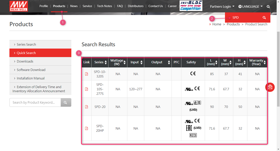
MEAN WELL offers a selection of Surge Protection Devices to protect the power supply against surges and voltage peaks.
- Select products
- Type in “SPD” in the search field
- You will find several available SPD’s
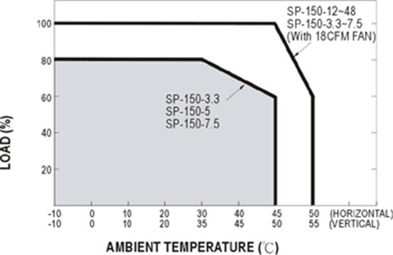
Most small wattage and fanless power supplies are mainly installed in the horizontal position. If you have to install it vertically because of mechanical limitation, you should consider the output derating due to the heat concern. The temperature derating curve can be found on the spec sheet. Regarding the power supplies with built-in fan or the application has forced cooling system, vertical and horizontal installations have less difference. Ex. In SP-150 derating curve, the ambient temperature difference in application is 5 Celsius from vertical to horizontal. The output wattage in forced cooling can be 20% higher than air cooling convection.
Depending on the cooling mechanism of the power supply there are different considerations and restriction towards the mounting orientation of the power supply and distance towards other components and self-heating components.
In general, please check our power supply user manuals on www.meanwell.com (Installation Manual-MEAN WELL Switching Power Supply Manufacturer). The actual distance and orientation depend normally on system design. Customers must review and test the power supplies in the real application and environment.
General guidelines for power supplies with different cooling mechanisms:
- Power supplies with an internal fan or which are cooled with an external fan have less constraints regarding the orientation in which they are mounted. Nevertheless, the fans and ventilation holes must be kept free from any obstructions. Also, a 10-15 cm clearance must be kept from any adjacent heat source
- A convection cooled power supply with standard a vertical mounting orientation which will be mounted in another orientation have to be derated by 5dC. See FAQ What should be noticed when installing a power supply in vertical and horizontal directions? Additionally ventilation holes must be kept free from any obstructions. Also, a 10-15 cm clearance must be kept from any adjacent heat source
- Din rail power supplies can only be mounted in the specified orientation. This is with the ventilation holes at the bottom and on top of the power supply. No other mounting directions are recommended. Allow good ventilation clearances, 5mm left and right, 40mm above and 20mm below, around the unit in use to prevent it from overheating. Also, a 10-15 cm clearance must be kept when the adjacent device is a heat source.
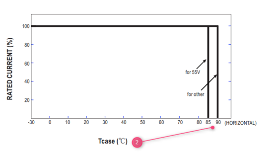
- For conduction cooling power supplies, the temperature on the Tc point is the key indicator if a mounting position can be allowed. The Tc position (1) and max Tc temperature (2) can be found in the product specification. Conduction cooled power supplies are for example IP65~IP68 LED drivers and base plate cooled power supplies such as UHP)
In MEAN WELL’s specification you can find 2 derating curves, in below example the 300W open frame power supply: EPP-300
- The Derating Curve with the Ambient Temperature vs. Load
- The Derating Curve with the Input Voltage vs. Load
- In this Curve one can find that the maximum load of this power supply is 300W at 50dC when an external air flow of 20.5CFM is applied. For temperatures exceeding 50dC, 60dC for example additional derating need to be applied, in above case at 60dC the maximum load would be 225W. (50dC 300W, 70dC 150W => from 50dC to 60dC: 75W derating)
- In case this power supply would be used at 90VAC input, a derating of 80% must be applied. So, in previous example with the 20.5CFM forced air the max load would be 240W. In case of an ambient temperature of 60dC and a 90VAC input the maximum rated power would be 225W * 0.8 = 180W with 20.5CFM forced air.
- If the power supply is used in an application without additional forced Air, the power supply will be derated to 200W till a maximum temperature of 50dC
- In case it will be powered by a 90VAC input the power supply has to be additionally derated to 80% of the 200W = 160W max
LED Drivers are recommended operate at full load as long as it observes the working temperature specified in the datasheet, which means Tc measurement results should be equal to or less than the stated Tc in the datasheet. 5 years warranty complies as long as drivers operate within working Temperature and Tc. Limit as well.
MTBF (Mean Time Between Failure) and Life Cycle are both indicators of reliability. MTBF can be calculated by two different methodologies, which are “part count” and “stress analysis”. The regulations, MIL-HDBK-217F Notice 2 and TELCORDIA SR/TR-332(Bellcore) are commonly used to calculate MTBF. MIL-HDBK-217F is a United States military standard, and TELCORDIA SR/TR-332(Bellcore) is a commercial regulation. MEAN WELL utilize MIL-HDBK-217F(Stress Analysis) as the core of MTBF. The exact meaning of MTBF is, after continuously using the power supply for a certain amount of time, the average time that the probability of proper operation is down to 36.8%(e-1=0.368). Currently MEAN WELL is adopting MIL-HDBK-217F, to predict the expected reliability through Stress Analysis (excluding fans); this MTBF means the probability of the product can continue the normal work after working continuously up to the calculated MTBF time is 36.8% (e-1=0.368). If the power supply is continuously used at double the MTBF time, the probability of proper operation becomes 13.5%(e-2=0.135.
DMTBF (Demonstrated Mean Time Between Failures) is a way of evaluating MTBF in a relatively short period of time based on accelerated deterioration (high stress, high temperature) tests under specific parameters and conditions. Please refer to the following equation for MTBF calculation.
This method compares to the previous methods, this calculation uses real test data to demonstrate the reliability of the power supply.
Where
MTBF: Mean Time Between Failure
- X2:Can be found in chi-square distribution
- N:Number of sampling
- AF:Acceleration factor, which can be derived from acceleration factor equation.
- Ae=0.6
- K(Boltzmann Constant)=(eV/k)
- T1:Rated temperature of specification. Note: Kelvin will be the unit use for calculation
- T2:The temperature that is used in the meaning of acceleration, and the chosen temperature could not result in physical change in materials.
Note: Kelvin will be the unit use for calculation.
Life Cycle (Capacitor Life Cycle) is found by using the temperature rise of electrolytic capacitors under maximum operating temperature to estimate the approximate life of the power supply. For example, RSP-750-12 MTBF=109.1K hours(25°C); electrolytic capacitor C110 Life Cycle=213K hours (Ta=50℃).
MEAN WELL considers the capacitor lifecycle calculation as the most important indicator for the estimated lifetime. The (D)MTBF is the main indicator for the reliability of the power supply. For more information please see: Investigation of The Lifetime & Reliability of Power Supply -MEAN WELL EUROPE Switching Power Supply