Hydrogen Energy and Power Supplies System
Global warming and extreme climate phenomena, net-zero carbon emissions have been the goal of countries in the world. Among alternative solutions for fossil fuels, Hydrogen Energy has attracted widespread attention.
The main reason is Green Hydrogen Energy with zero carbon emissions which has significant application opportunities in the fields of renewable energy, industry and transportation. Therefore, hydrogen energy is considered one of the key solutions to address energy issues.
Hydrogen Types
Hydrogen atoms are present in common compounds such as water, methane and ethanol. Currently, there are two hydrogen production technologies: Electrolysis and Steam Reforming. According to hydrogen production methods and carbon emissions, hydrogen can be categorized into Grey Hydrogen, Blue Hydrogen and Green Hydrogen, as shown in Figure 1.
Grey Hydrogen is the most common way of producing hydrogen. The raw materials for hydrogen production are fossil fuels such as coal, oil and natural gas. The cost of converting hydrogen through chemical reactions is relatively low. However, this method generates a significant amount of carbon dioxide emissions. Similar to grey hydrogen, Blue Hydrogen also uses fossil fuels to produce hydrogen. However, it incorporates carbon capture processes to capture and store the produced carbon dioxide, which can reduce carbon dioxide emissions. Green Hydrogen utilizes renewable energy to electrolyze water, producing hydrogen with almost no carbon emissions in the process. Therefore, it is the most environmentally friendly way to produce hydrogen.

Figure1. Hydrogen Types
Introduction of Electrolysis Hydrogen and Fuel Cell
The field of hydrogen energy can be divided into electrolysis hydrogen production and fuel cell applications. Commonly used electrolysis hydrogen production technologies include [1-2]:
1) Polymer electrolyte membrane electrolysis, PEM-EL: It uses a solid acid polymer membrane as the electrolyte. Water is electrolyzed at the anode into hydrogen ions and oxygen and releases electrons. Hydrogen ions migrate to the cathode through the proton exchange membrane and combine with electrons conducted by the external circuit to generate hydrogen gas. This technology has the advantage of high electrolysis efficiency due to its high current density characteristics. The cell voltage range of PEM electrolyze is between 1.8 V and 2.5 V.
2) Alkaline electrolysis, A-EL: It uses potassium hydroxide as the electrolyte. Hydroxide ions migrate to the anode through the porous conductive membrane, where they undergo an oxidation reaction to release electrons to generate oxygen. Water is electrolyzed into hydrogen ions and hydroxide ions at the cathode and accepts electrons to release hydrogen. Currently, it is mainly used in large-scale electrolytic hydrogen production systems. The cell voltage range of AEL electrolyze is between 1.4 V and 3.0 V.
3) Anion exchange membrane, AEM-EL: It combines the low cost of an AEL with the simplicity and efficiency of PEM. Using non-noble metal catalysts and titanium-free components, it can operate under pressure differences like PEM. AEM has low conductivity, slow catalytic kinetics and poor electrode structure which affects the performance of AEM. The cell voltage range of AEM electrolyze is between 1.4 V and 2.0 V.
4) Solid oxide electrolysis, HT-EL: It uses ceramic materials that conduct oxygen ions as electrolytes. Water enters the electrolyze in the form of steam and it is electrolyzed into hydrogen ions and oxygen ions at the cathode. The hydrogen ions accept electrons conducted by the external circuit to generate hydrogen. This electrolysis method operates in a high temperature environment (700~1000℃). The cell voltage range of SOE electrolyze is between 1.0 V and 1.5 V.
Currently, electrolytic stack modules are mostly customized and towards high power development. Figure 2 is a structural diagram of an electrolytic stack. For example, a cell voltage is 2V and 48 cells are connected in series to form a 96V stack, which means a DC 96V power supply is required for electrolysis. Therefore, a longer stack length with a higher voltage is required. A larger number of stacks in parallel and a larger surface area imply that hydrogen electrolysis requires a higher electric current.

Figure 2. Structural diagram of an electrolytic stack
The hydrogen produced through electrolysis is transported either via hydrogen storage tanks or pipelines to various application sites. Currently, the most widely used application is in fuel cells. The fuel cell stack is composed of multiple plates and membranes. After adding hydrogen and oxygen into fuel cell, the chemical energy is converted into electrical energy for use. Fuel cells produce a typical voltage of around 1V. Stacking these cells creates a higher usable voltage. Currently, fuel cell stacks are mostly customized to fit various applications. Fuel cell types include phosphoric acid fuel cells (PAFC), molten carbonate fuel cell (MCFC), alkaline fuel cell (AFC) and proton exchange membrane (PEM) cell.
Figure 2. shows the fuel cell polarization curve [3]. As the current increases, the first voltage drop represents a loss of cell activation. The second part represents the voltage loss caused by internal resistance. The third part represents the voltage drop due to gas delivery or concentration loss. Table 1 shows a comparison of fuel cell stacks specifications from various manufacturers. The characteristic of a fuel cell stack is that the voltage decreases as the operating current increases. More stacks in a fuel cell stack means a higher power output of the fuel cell.

Figure 3. The fuel cell polarization curve [3]

Table 1. Comparison of fuel cell stacks specifications from various manufacturers
Hydrogen Energy Systems and Power Supplies Requirements
Figure 4. shows the hydrogen energy system and power supplies requirements [4], which can be divided into two applications: electrolysis power supplies and fuel cell power supplies. Electrolysis power supplies can be converted into electrical energy by grid-connected AC/DC converters, wind turbine AC/DC converters, solar DC/DC converters and battery DC/DC converters for electrolysis hydrogen. After a fuel cell generates electricity, it can be converted to the load through a DC/DC converter or a DC/AC inverter. In the selection of the electrolysis power supplies, constant current and programmable current control functions of power supplies are needed. In the selection of fuel cell power supplies, wide input voltage range and high-power rating of power supplies are requested, and the user should note that fuel cell stack voltage decreases with using life and ageing.

Figure 4. Hydrogen energy system and power supplies requirements
The feature of MEAN WELL power supplies is that a single model has multiple voltage models with a wide voltage range design to fit market applications. Users can achieve programmable output voltage (PV) and programmable output current (PC) functions for power supplies, which can be implemented through the communication interface and external voltage. The selection of power supplies for electrolytic hydrogen production can be divided into modular power supplies and centralized system power supplies. Figure 5. shows the modular power supplies used in electrolysis hydrogen. Taking MEAN WELL AC/DC power supply products DPU-3200 series and PHP-3500 series as an example, a single power supply can be used to correspond to one electrolytic tank to form a module. Modular power supplies provide more flexibility, allowing users to choose multiple independent modules or multiple parallel modules for high-power electrolysis hydrogen based on system power or configuration requirements.

Figure 5. The modular power supplies used in electrolysis hydrogen
Figure 6. shows applications of centralized system power supplies for electrolysis hydrogen. Taking the NCP-3200 series and SHP-30K series AC/DC power supplies as examples, they can be divided into two solutions: Single-phase AC and 3-phase AC input:
- Single-phase AC input : NCP-3200 series + DHP-1UT-B(HV)shelf + Controller_CMU2 + Rack Cabinet.
- 3-phase AC input : SHP-30K series + Controller_CMU2 + Rack Cabinet.
Above MEAN WELL (3+N) centralized system power configurations can provide up to 360KW. Multiple centralized system power supplies can also be configured according to factory requirements to achieve multiple high-power electrolysis hydrogen. Following with MEAN WELL AC-DC power supplies solutions for electrolysis hydrogen.

Figure 6. Applications of centralized system power supplies for electrolysis hydrogen
| Modular Power Supplies | |||
|---|---|---|---|
| 1): 3200W; Single phase AC input | 2): 3500W; Single phase AC input | ||
| DPU-3200 series | PHP-3500 series | ||
 |
DC output: 24V, 48V |
 |
DC output: 24V, 48V, 115V, 230V, 380V |
| (3+N) Centralized system power supplies | |||
| 1): Max. 320KW system power; DC output: 24, 48, 380VDC; Single phase AC input | |||
| NCP-3200 series | DHP-1UT-B (HV) | CMU2 | 19” Rack Cabinet |
 |
 |
 |
 |
| 2): Max. 360KW system power; DC output: 55, 115, 230, 380VDC; 3 phase AC input | |||
| SHP-30K series | CMU2 | 19” Rack Cabinet | |
 |
|
|
|
| 3): Others PSU; DC output: 55, 115, 230, 380VDC; 3 phase AC input | |||
| RST-15K series, SHP-10K series | CMU2 | 19” Rack Cabinet | |
  |
|
|
|
Table 2. MEAN WELL AC-DC power supplies solutions for electrolysis hydrogen
Figure 7. is an example of hydrogen electrolysis power supplies control. MEAN WELL (3+N) centralized system power supplies are used to perform hydrogen electrolysis with stacks. During the initial electrolysis process, the system power supplies current is adjusted according to the internal impedance and gas reaction of the electrolytic tank. Power supplies current changes from low current to high current over time to perform electrolysis. The advantage of MEAN WELL system power supplies is that the programmable output current (PC), which has an adjustable wide range, is 20%-100% of the load. Therefore, the system controller can control MEAN WELL system power supplies to perform electrolysis at a lower current level through communication. During the electrolysis process, the system controller will detect the parameters of gas and output current and output voltage of power supplies at any time into the system control loop, and then the system controller can control MEAN WELL system power supplies through communication to adjust the output current and voltage to achieve the optimal electrolysis efficiency.

Figure 7. Example of hydrogen electrolysis power supplies control
An example of fuel cell power supplies is shown in Figure 8. The characteristics of the fuel cell stack are a wide voltage range, and the voltage range of fuel cell stacks varies among different manufacturers’ designs. Therefore, taking MEAN WELL wide voltage range DC/DC power supplies DDRH series as an example, power energy generated by fuel cell will be converted into low voltage through the DDRH series high-voltage DC/DC converter and supply to various loads such as fans, DC motors, controllers and LCD monitor applications.
Generally, fuel cell systems will also be equipped with another high-power DC/DC converter to store the fuel cell energy into backup battery storage system for other DC loads. The new product of MEAN WELL is preparing to launch, the 2 in 1 design of high-power charger/Inverter with UPS, NTN-5K series, highlights its advantages. The wide DC input voltage range of DC/AC inverters can fit fuel cells applications. Inverter converts DC power into AC power, it can also support single-phase AC or 3-phase AC 90KW system applications through parallel connection. Table 3. shows MEAN WELL DC/DC and DC/AC power supplies for fuel cell solutions.

Figure 8. Example of fuel cell power supplies
|
DDR series |
|
DC input: 16.8-33.6V; 33.6-67.2V; 67.2-154V DC output: 12V, 24V, 48V 4 units parallel application |
|
|
DDRH series |
|
DC input: 250-1500V DC output: 12V, 24V, 32V, 48V 4 units parallel application |
|
|
RSDH series |
|
DC input: 250-1500V DC output: 12V, 24V, 32V, 48V |
|
|
SD series |
|
DC input: 19-72V or 72-144V DC output: 12V, 24V, 48V |
|
|
NTS series |
|
DC input: 10-16V, 20-33V, 40-66V AC output: 100-120Vac; 200-240VAC Inverter function |
|
|
NTN series |
|
DC input: 20-33V, 40-66V, 280-430V AC output: 100-120Vac; 200-240VAC Build in inverter/charger with UPS |
|
|
*For more details, please refer to MEAN WELL Virtual Expo |
|||


Table 3. MEAN WELL DC-DC and bidirectional DC-AC power supplies for fuel cell solutions
Conclusions
The feature of MEAN WELL power supplies is that single model has multiple voltage models with a wide voltage range design to fit market applications. Users can achieve programmable output voltage (PV) and programmable output current (PC) functions for power supplies which can be implemented through the communication interface and external voltage. Figure 8 shows the application combination of the hydrogen energy system and MEAN WELL power supplies. MEAN WELL power supplies have deployed AC/DC modular and 3+N system power products in the field of electrolytic hydrogen with a maximum capacity of up to 510 kW. DC/DC power supplies can provide up to 2KW and DC/AC inverter power supplies can provide up to 90KW for fuel cell applications.
Currently, MEAN WELL can provide more power supplies solutions based on customer application needs in the field of hydrogen electrolysis, fuel cells and renewable energy. For inquiries about related products and application requirements, you can directly contact MEAN WELL sales or technical staff. In addition, please stay tuned for MEAN WELL online exhibition hall relevant products and online courses for solutions.”

Figure 9. Application combination of the hydrogen energy system and MEAN WELL power supplies
References:
[1]. Energy Administration, Ministry of Economic Affairs, R.O.C,再生能源電解產氫之技術發展狀況。
[2]. 太原麗子,電解產氫技術簡介及日本發展現況研析。
[3]. H. E. A, A. C, C. S, A. P. N and E. G. “Thermal and Electrical Parameter Identification of a Proton Exchange Membrane Fuel Cell Using Genetic Algorithm”, 2018.
[4]. Hydrogen Technology Expo Europe 2023.
Learn more about Power Supplies used in Hydrogen
Explore our blog for insightful technical notes about Hydrogen Energy and Power Supplies.
Got questions?
Look at the section below to find the most frequently asked questions (with answers)
we received in Hydrogen Applications.
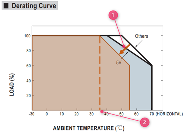
Yes, for power supplies certified >2000m please read the “note” in the spec.
In general, for unpotted models, a derating of 5°C/1000m has to be applied and for potted models, a derating of 3.5°C/1000m has to be applied.
For example LRS-75-24:
The datasheet shows:

The Note. 7 shows:

At 5000m the derating curve will need to move 15°C following the arrow (1)
At full load the maximum operating temperature at 5000m will be 35°C shown at (2)