Introduction
Designing a Complex Medical Device that requires Patient Contact might be not an easy task, also for a Senior Power Supply Engineer.
Multiple Voltages are required, Low leakage and High Isolation is mandatory (often also between channels to minimize cross interferences). Multiple motors, heaters, coolers, and other electronics boards must be powered at the same time, often requiring High Power Converters (several KW). Because of Low Audible Noise requirements, Fan-Less solutions are often requested.
What type of approach MEAN WELL advises then?
Main requirements for a medical power supply used in a Medical application are Isolation and Ground Leakage:
- The Isolation requirements limit us in the type of Power Supplies we can use (typ. only medical approved can pass this test).
- There are two level of typ. Isolation requirements MOOP (for operators) and MOPP (for patient).
The Ground Leakage requirements limit us in the number of Power Supplies we can install in the application (leakage currents sum-up).
| Classification | Level | Isolation | Insulation |
| 1x MOOP | Operator | 1500Vac | Basic |
| 2x MOOP | Operator | 3000Vac | Double |
| 1x MOPP | Patient | 1500Vac | Basic |
| 2x MOPP | Patient | 4000Vac | Double |
Considering the limitations of Isolation and Leakage, in case of Complex System Requirements, the number of Medical Power supplies that it is possible to use is limited.
Nevertheless, we should not forget that Isolation and Leakage are defined at System Level, this is a good way to overcome the limitations.
In this article, we will go thru 1 specific case study and we will try to analyze 3 possible solutions, checking the pro and cons.
We will also show how it is possible to use Industrial solution in some specific Medical Applications. Even if the final application will require extra safety test by the external labs, often the final solution is worth the extra efforts, both in terms of performance and cost.
Solutions we will analyze:
- Use of Isolation Transformer
- Use of AC-DC Front End + Multiple DC-DC Converters
- Use of Class II Power Supplies
Case Study
A Medical application (Dental Chair) requires:
- 600W @ 24V – 1000W peak 10Sec – 2x MOOP
- 60W @12V – 2x MOPP
- 60W @12V – 2x MOPP
- 60W @12V – 2x MOPP
- (all outputs isolated)
- Leakage < 300uA
- 230Vac Input
- NO FAN
- UL/CE
The total Wattage Requirements (1180W) would have required the use of multiple Power Sources or a modular Power supply.
But:
- We cannot use Multiple PSUs because of Low Leakage Requirements
- We cannot use Modular Power Supplies because of the “NO FAN” limitation
Solution 1: Use of Isolation Transformer
The use of an Isolation Transformer allows us to increase the total Isolation of system, minimizing the risk of electric shocks (as visible is figure 1) and reducing to almost Zero the Earth Leakage of the System (for the devices connected after the transformer). Isolation tranformers might also improve the Conducted EMC performace of the system.
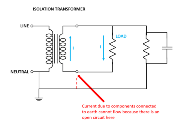
Figure 1 Isolation Transformer
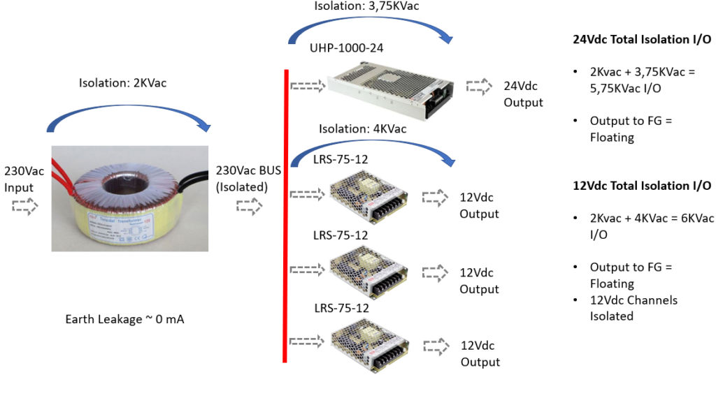
Figure 2 Complete solution with Isolation Transformer
To sum up, using an Isolation Transformer, we are able to:
- Use multiple PSUs (leakage is almost zero in fact)
- Use Non-Medical Power Supplies (the Isolation Transformer provides the extra isolation we need)
- Easily improve Isolation in our system
On the other side we have:
- An extra (heavy) component
- Extra space needed
Solution 2: Use of AC-DC Front End + Multiple DC-DC Converters
Introducing a transformer on the input has allowed us to increase the isolation level and reduce to almost zero the leakage current.
Another solution that we could adopt to increase the isolation without increasing the leakage current is to introduce, after the first AC-DC, several DC-DC converters.
Anyhow introducing DC-DC converters is not as easy as it could seem. First, and most important, we must take a deep look at the Ycaps to be sure that the system can pass the Hi-Pot test. (Fig. 3).
Second, we must take care of the peak current required by the DC-DC at the start (if the AC-DC is too small in terms of max current, it could go in protection).
In our specific case, a good solution could be the use of one UHP-1500-24 as front-end (1500W – Baseplate Cooled – 0.75mA max earth leakage)
If you wonder why we are using an industrial PSU as front-end, the specs require for the main channel only MOOP, hence, an industrial PSU with proper isolation level between primary and secondary is sufficient.
For the other Channels, it is possible to introduce 3x DC-DC converters like our DDR-60G-12 (4KVdc isolation, Class II, 4:1 input range). In this way we can increase the isolation without increasing the leakage (they are Class II) and because of the high level of isolation (4KVdc) we are sure that we will not have any issues with Hi-Pot Test. Configuration is visible in fig. 4.
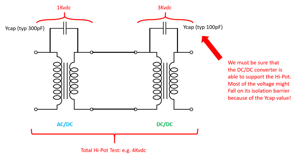
Figure 3 Hi-Pot Test voltage distribution in case of DC-DC converters use after AC-DC
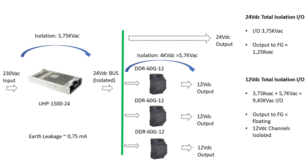
Figure 4 Complete solution with DC-DC converters
To sum up, using multiple DC-DC converters, we are able to:
- Easily improve Isolation in our system
- Reduce the complexity of our system
- Reduce the total size
- Reduce the total leakage
On the other side we must:
- Select with care the proper AC-DC and DC-DC to make sure proper Isolation level is reached also during Hi-Pot test. (please always refer to MW sales team to get a proper advice on the right Power Unit – DC/DC converter)
- Over dimension the AC-DC to also support the DC-DC input current
Solution 3: Use of Class II PSUs
The solution with multiple DC-DC converters is handy but obliged us to use an UHP-1500-24 instead of a UHP-1000-24. This to support the extra load coming from the DC-DC converters. We do not have any information about the contemporaneity factor, so we must consider the worst case: all the outputs used at max wattage at the same time.
How could we reduce the cost? In this specific case, considering the low wattage of the MOPP outputs, we could consider using multiple Medical CLASS II AC-DC converters to meet the requirements and reduce the total cost of the solution. MPM-65-12ST is perfect for this purpose. It is a 65W Class II 2xMOPP PSU that will allow us to create 3 separate 12V channels without increasing the total Leakage Current. For the main Channel, we can use the UHP-1000-24 that can support 2x MOOP (requires external lab. approvals being an industrial PSU).
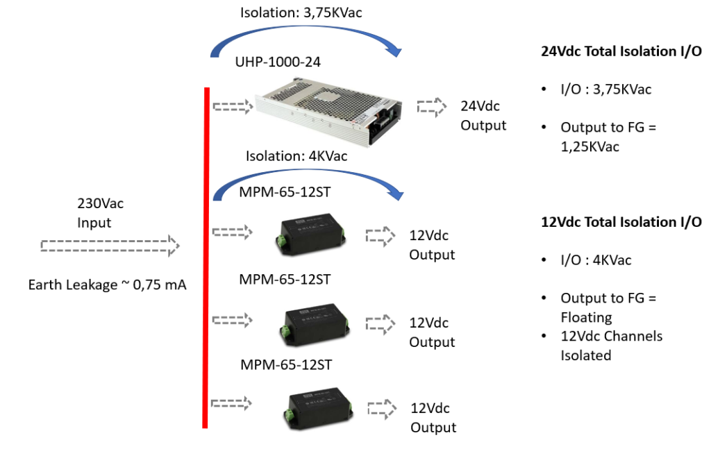
Figure 5 Complete Solution with Class II Power Supplies
To sum up, using Class II PSUs, we are able to:
- Reduce the complexity of our system
- Reduce the total size
- Reduce the total leakage
- Reduce the cost (in this specific case study)
On the other side we must:
- Take care of the EMC performance of the system (often Class II PSU might not perform well in Class I applications)
- Important: please always refer to MW sales team to get a proper advice on the right Power Unit
Conclusions
Solution 1
provides more flexibility in terms of Power Supplies that is possible to use. The transformer in the front takes care of the main Isolation, so it is possible to use pure industrial power supplies after it. It is a good solution in extremely complex/high power solutions and were extremely low leakage is required. Transformer in the front also helps to improve the overall EMC performance.
Solution 2
is perfect in all the cases it is not possible to install multiple power supplies and we do not want to install a transformer in the front. Requires a bit of attention during the selection of components (we must be sure we can pass the hi-pot test) but it is pretty flexible and allows the designer to increase the overall isolation without increasing the leakage.