Building Automation System
Building Automation System (BAS), also known as Building Management System (BMS), is an intelligent system for modern buildings. These systems offer monitoring functions and enhanced control over electrical and mechanical systems throughout a building. A Building Automation System enables users to control lighting, heating & cooling (HVAC), shutter, security, and many other applications. A well setup BAS will help to run HVAC systems and lighting system more efficiently and reduces energy consumption.
In the current market, several popular control systems exist, such as BACnet, Modbus, DALI and KNX, each with its own benefits and limitations. Depending on the purposes and objectives of the building or smart home, one control system is often customized to meet the specific demands of each situation.
One of the most complete Building automation control systems widely adopted in Europe is KNX. This system offers a uni-communication design between controllers, sensors, and actuators. KNX is specially targeting building, home automation and domotics projects and is one of the few systems which offers solutions to every automation aspect (e.g., HVAC, Acces Control, Sensors, security and lighting) in a Building Automation System.
MEAN WELL KNX PRODUCTS
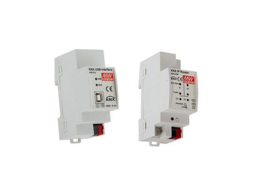
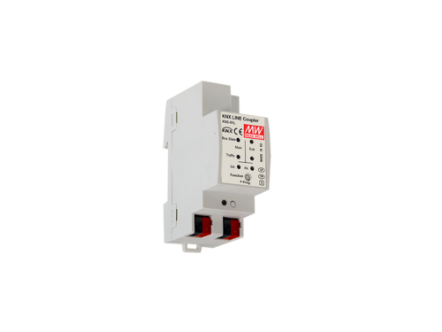
MEAN WELL is the leading manufacturer of Standard Power Supplies in the market. With over 40 years of experience in the development and production of power supplies, MEAN WELL offers a wide range of high-quality KNX devices in 6 categories as below.
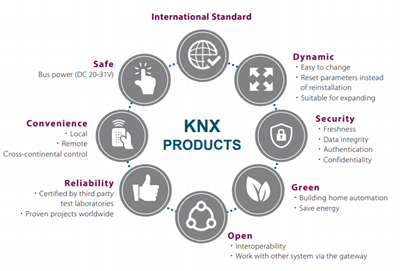
What are benefits of KNX?
KNX is an international recognized standard which covers every automation aspect of home and building control. This standard is adopted by more than 500 members. Some of the key benefits of KNX are:
- Excellent compatibility between KNX devices from different manufacturers
- Endless different automation solutions available in the market (over 10.000 certified KNX products are available)
- Manufacturer independent software (ETS)
- Future proof technology
- Secure system options available
- Easy integration into other BAS (sub)systems, such as Modbus, BACnet & DALI
- Large community and high acceptance rate
- Effortless installation and endless possibilities to expand
With KNX system, users are nowadays able to control all kinds of application devices under the roof of their smart building. KNX IoT (Internet of things) further allows the users to control via KNX app from mobile devices to achieve KNX wireless, which is communicated via KNX IP or KNX RF. Setting up lighting and heating of the building is easier than ever: blinds can now be shut, doors can be locked with one simple touch on the screen. Not only have living and working environments become more convenient and secure, but they are now also more energy-efficient and economical.
What is KNX Secure?
In response to the rising demand of data protection, KNX Secure technology is designed to protect all system data accordingly to the highest encryption standards. KNX Secure signs and encrypts the communication telegrams in the KNX network to avoid the manipulation by unauthorized access or hackers.
The KNX Secure protection is designed in two layers: KNX data secure and IP secure; the former one protects principally the user data against unauthorized access and manipulation, while the latter one aims to ensure that all communication telegrams and data are securely encrypted.
The secured communication data includes the commissioning (configuration) processes with the ETS software, as well as the runtime (daily) communication between KNX devices. The concept ensures that all or selected KNX telegrams are authenticated and encrypted regardless of the medium.
As result, the communication between sender and receiver can be neither interpreted nor manipulated.
KNX Lighting Control
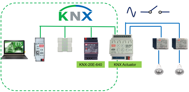
The architecture of the KNX lighting system consists of KNX power supply that supplies the KNX bus and KNX switch actuator which is used to control the LED driver by simply turning on or off. In addition, a KNX presence detector can also be installed to automatically control the light when human or moving objects have been detected.
KNX lighting control systems can be divided into two types: Analog lighting systems and Digital lighting systems. Analog systems tend to be more flexible when it comes to the control over lighting devices, whereas digital lighting systems have as advantage more comprehensive control and the possibility to read out data from the KNX device directly such as power consumption and lamp failure.
Analog lighting systems are in general a combination of KNX actuator, KNX dimming actuator and/or KNX phase cut actuators. These actuators are powered and controlled via the KNX bus and can switch on/off the AC mains by means of a relay. Whereas dimming is achievable by a 0-10V/1-10V signal or by cutting of a phase.
Main advantages of these analog systems are that, in principle, any type of drivers or ballasts can be connected to the KNX actuator, and that a single KNX actuator would allow to switch on all connected fixtures, ballast and or drivers.
Disadvantages of analog systems are that additional wire installation is needed to transfer the 0-10V/1-10V signal, so different wire lengths could result in different light output of the light source, and there could be compatibility issues between KNX Phase cut actuator and phase cut driver.
Currently, there are few options available to make a direct digital lighting control in KNX (or other BAS) systems. The most common solution for a digital lighting system implementation in a BAS is by using a subsystem, and one of the most accepted digital lighting systems is DALI. DALI is an open protocol focusing on lighting control and is accepted by most lighting manufacturers. To create a subsystem in a KNX system, a KNX DALI Gateway is needed to translate KNX commands into DALI commands.
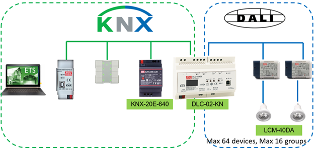
Advantages of Digital Lighting System:
- Easier installation and less wires as it is a bus system with addressable components
- Light levels can be controlled precisely and will be consistent despite the cable lengths
- Read data (Lamp failure, Power consumption)
- Emergency function
- CLO light compensation (LED’s age over the time and CLO will compensate the light output)
- Logarithmic dimmable
- Color control and complex scene setting
Disadvantages of Digital Lighting System:
- Higher cost of the components in the system
- Knowledge is needed for setting up ETS and DALI
- Additional gateway needed
- Gateway is a single point of failure
KNX Direct Digital Lighting Control
One of the drawbacks of using a subsystem for Digital lighting control is the need of gateways which generates additional costs and creates a single point of failure in a digital lighting system. Also, one would need to have the knowledge of 2 different protocols to set up the lighting system.
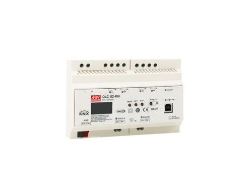
One should consider why using 2 different protocols when the KNX protocol has all functions to make a direct digital control over a lighting system? MEAN WELL is one of the first manufacturers offering KNX LED drivers which can be controlled directly over the KNX BUS. This is an economical solution as it simplifies the installation by using a single protocol, saving cost of KNX Dali Gateway and removing single point of failures.
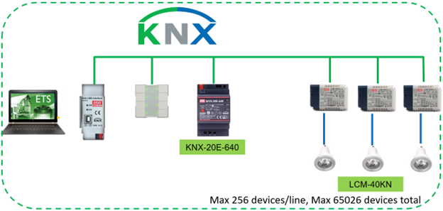
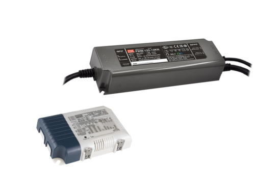
MEAN WELL KNX LED drivers are available as constant current drivers (LCM-25KN, LCM-40KN and LCM-60KN) and constant voltage dimmable LED drivers (PWM-60-KN, PWM-120-KN and PWM-200-KN) with a PWM frequency which can be setup up to 4kHz. The details of these drivers can be found here: KNX Building Automation Solution-MEAN WELL
More information about digital lighting control: Better than DALI: KNX Lighting – All About MEAN WELL Power Supplies
Blind Control with KNX
A KNX blind control or KNX shutter control system is an important element in creating an efficient energy-saving system in modern smart buildings.
Blind and shutter control systems are usually triggered by data provided by KNX Room controllers, KNX Weather stations and/or KNX Light Sensors. Based on the inputs of these devices and the settings made in the ETS software, KNX shutter actuators are triggered to set blinds and shutters in optimal positions to provide energy efficiency, shading and visual comfort.
A simple example of a blind control system is a light sensor installed to measure the sunshine radiation value of a specific indoor space. With collected data, a KNX shutter actuator is programmed via ETS software to control the shading system: when the sunshine is strong, the corresponding blinds or curtain of the wall will be closed to provide shielding, and vice versa.
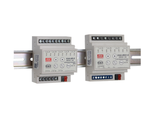
KNX shutter actuators are the key element in KNX Blind control systems, ensuring the comfort of the indoor environment and promoting the energy efficiency of the smart building. For this, MEAN WELL offers the compact-sized KAA-8R which can control electrical shutter, blinds or curtains systems.
Heating and ventilation System Control with KNX
KNX is the leading system to create an intelligent controlled heating and ventilation and Air-conditioning (HVAC) system. In the market, there are many KNX HVAC solutions available, such as KNX room temperature controllers, Fan Coil controllers and temperature sensors which form the input to manage KNX heating actuators, KNX valve controls, KNX ventilator controller, actuators, and many more to manage climate and environment efficiently and comfortably inside buildings.
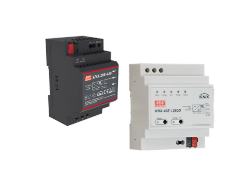
Efficient KNX HVAC systems can consist of a KNX temperature sensor to measure the temperature value of the office or a specific indoor space. With these values, a logic controller can control the heating system and adjust the room temperature. To meet this kind application, MEAN WELL has developed the KNX bus power supply KNX-20E and KNX-40E to provide KNX equipment power. The KNX switch actuator, KAA-8R can control the heating circuit and switch on/off the heater on the heat sink or in the underfloor heating system. Depending on the device model and parameter settings, the heating system can be controlled via switching parameters or pulse width adjustment (PWM). It is not only suitable for private residences, but also for commercial building usages, such as office buildings, schools, and hotels.

MEAN WELL KNX system product line consists of KNX power supply for KNX bus network, KNX-DALI gateway and KNX-LED drivers. For flexible building management, MEAN WELL KNX actuator can be used to control lighting and HVAC systems. MEAN WELL is the industry leader for industrial power supplies, and offers a complete portfolio of power supply solutions for smart building installations such as the compact and highly efficient HDR series in 15W/30W/60W/100W/150W. To sum up, the portfolio of MEAN WELL KNX system is the intelligent solution for networking, controlling, and powering Smart Buildings.
LEARN MORE ABOUT MEAN WELL KNX SYSYEM
Explore our blog for insightful technical notes about KNX Building Automation Applications.
Got questions?
Look at the section below to find the most frequently asked questions (with answers)
we received in Building Automation Applications.
The GTIN number can be found directly on the www.meanwell.com:

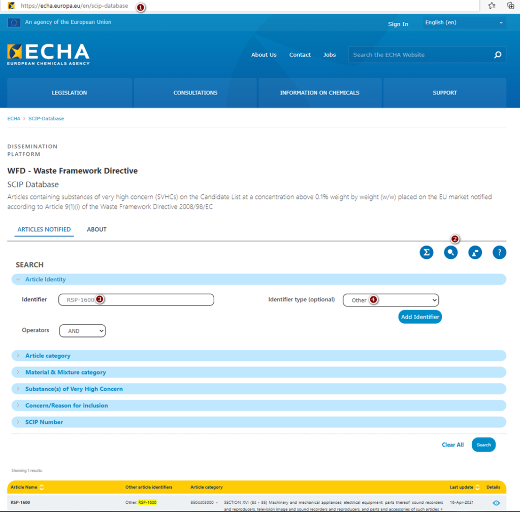
Yes, MEAN WELL products are registered in SCIP. To get such information for specific power supply, please follow the steps below:
- Go to https://echa.europa.eu/en/scip-database
- Under SEARCH option, choose „Article Identity” and write down model name e.g. RSP-1600.
- As “Identifier type (optional)”, please chose “Other”
- Click “Search” button
The declaration of Five PBT TSCA Conformity can be found on the last page of Installation Manual e.g. below:

A Surge Protection Device is optimized for a single voltage. Therefore, SPD should be chosen according to the actual operating voltage of the part that need to be protected.Secondly, the voltage protection level shows what is the maximum voltage appeared at output side when a specified surge is coming to the SPD. In general, the lower the voltage protection level, and the higher the discharge or surge current from SPD, means the better protection that the SPD provides.
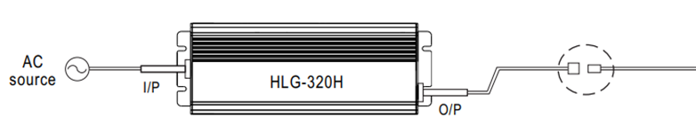
Owing to line (voltage)-drop, we suggest the extension made from AC cable. In case DC cable extension is necessary, please consider Line-Drop leading to insufficient Vf so that the LED model or lamp may fail to switch ON. Moreover, EMC performance and characteristic may also be affected by DC cable extension.
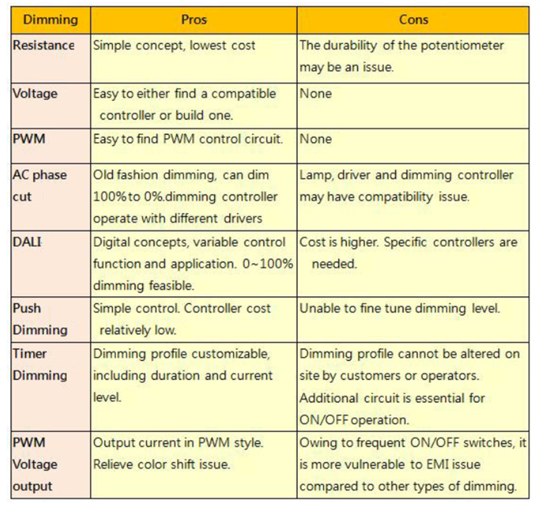
There are so many MEAN WELL dimming products. How can I make a choice? What are the pros and cons?
First, you have to know your Led lamp specification in order to screen out a suitable Led driver range (Wattage, Voltage, Max Current CC or CV). From those ranges, further check a compatible dimming function. Hereunder is a table to show you the pros and cons of Dimming Function you can find in MW’s catalogue.
MEAN WELL has several charger products, and we suggest choosing them first. Chargers would be more suitable since they are designed for charging applications. Safety and approvals should be taken into account based on the final application. If you are unable to find a proper model in our charger series, our LED CC models can be used as charger. Please choose suitable products after confirming the current and voltage specification on the datasheet of the battery.
3 in 1 dimming circuit would drain 0.1mA per model. Dividing the rated current of the dimmer by the 0.1mA, and we could know how many units can be controlled by one dimming device. For resistance dimming applications, resistance for 100% dimming output would be 100K ohm divided number of models.
A LED strip is normally a Constant Voltage application (CV). For this type of CV application MEAN WELL has design the PWM, IDLV and ODLV series which will allow CV applications to dim.
3 in 1 dimming is the most common application used in LED dimming with the feature that it does not have to work with any specific dimmer. The only thing that has to be verified is that whether the dimmer (1~10V/10V PWM/resistance) is compatible with the definition advised in our specs.
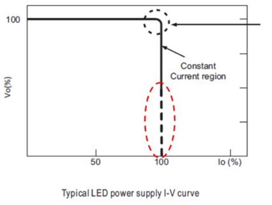
MEAN WELL’s LED product specification normally exhibits V-I characteristics. Per the characteristics, there are generally two types of drivers, the “CC” type and the “CC+CV” type. “CC” type of driver is suitable only for LED applications whereas “CC+CV” is for either LED applications or general switching power supply applications. The section that is not suitable for LED applications are represented by dotted line, and based on the protection procedures it can be categorized into hiccup mode and constant current mode; in this section, the tolerance of current is not defined but only the characteristic of current is displayed. If customers attempt not to see a very high current under short circuit conditions, those models with hiccup mode for this section can be selected; if there are applications with motors or capacitive load, those with constant current can be chosen.
There are 2 types of Power Factor Correction circuits; one is Single Stage; the other is Two Stage.
Single Stage power supply combines functions of power factor correction and converter in one circuit but Two Stage use two separate circuits. Compared to Single Stage, Two Stage design is more complex and costly, but the immunity performance of Two Stage power supply against AC mains is much better than that of Single Stage power supply. In addition, Two Stage power supplies manifest better ripple noises performance on output. Owing to that Single Stage is only suitable for fields with quality AC mains but Two Stage can be used in serious circumstances for LED drivers or as industrial switching power supplies.
Depending on the installation environment, you may need IP certified power supplies (IP65/IP67).
Also, waterproof connectors and junction boxes are useful accessories to ensure a reliable operation in damp environments (please refer to the LED power supply installation manual).
Waterproof connector solution
Junction box option
Note that the MEAN WELL product IP level, including IP67, is tested according to IEC 60529. The protection does not guarantee for permanently immersing in the water. Please check the device installation manual for proper suggestions on installation.
MEAN WELL developed many power supplies series specifically for LED application. Single stage PFC was used in such developments due to low cost. This topology has the following restrictions:
AC fluctuation
- This topology does not use input bulk capacitor. For this reason, in areas with low AC quality, output voltage and current may become unstable causing variation in LED brightness. If the input AC voltage is stable, then this problem will not occur.
- Output ripple
This is also caused by lack of input bulk capacitor. As compared to power supplies using two-stage PFC, the ripple will be significantly larger (see Figure 4). There could be instances where the low end of the ripple may be too low for the driver IC to operate properly, and the LEDs will start to flicker. To solve this type of problem, the output voltage can be adjusted higher, so the low end is higher than the driver’s minimum working voltage. Or simply select a PSU with higher rated voltage.
- Current harmonics
Single stage PFC power supplies are optimized for constant current drive. Using these supplies as constant voltage sources (such as application including cascading a constant current driver IC), the harmonics might be worsening in this case. When operating in areas with unstable utility voltage or with driver IC, we highly recommend using general application types as found in table 1. Avoid using single stage PFC if possible and use a two-stage PFC power supply instead, or contact MEANWELL for more information.

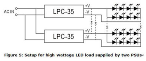
MEAN WELL LED power supply does not have a parallel “current sharing” function, so it is not suitable for parallel connection. For high power requirements, please select higher wattage power supply or divide LED load into smaller subsections to be powered by individual power supplies. Example of such LED configuration can be found in figure 5. As shown in fig. 5, the connection between -V of the LPC-35 units should be severed and not connected in common. On the contrary, small wattage LED loads can be connected in parallel and be powered by a single high wattage power supply. But the ability to divide current evenly must be taken into consideration.
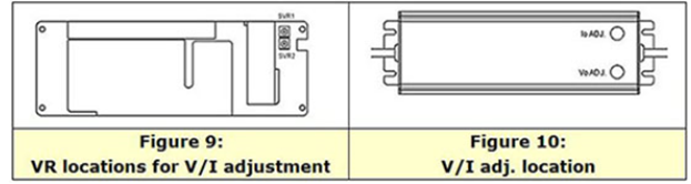
LED power supply comparison table to see which MW LED power supply allows for V/I adjustments. A suitable unit can be picked based on the type of adjustment required. For the allowed adjustment range, please refer to the spec sheet. Tuning of the voltage and current levels can be done through the built-in VRs/potentiometers. PLN/ELN requires removal of the top cover in order to access the internal SVR1 and SVR2, see figure 9 for VR locations. For other series, the VRs can be accessed through IoADJ and VoADJ holes after rubber stopper removal. After adjustments have been made, please make sure rate power is not exceeded and the rubber stoppers are properly reassembled.
With 1~10V dimming, the lighting unit can be dimmed down to 10%; with 0~10V dimming, it can be dim down to 0%, or say, dim-to-off.
Depending on the circuit design, there could be different operational problems. See below:
- Boost mode driver IC:
The startup voltage of such driver IC is significantly lower than the total LED forward voltage. For this reason, the IC will start up at very low voltage level usually about 1/2 of the power supply’s rated voltage and to meet rated power requirement, the startup current will reach 2 times the power supply’s rated current. When the power supply is unable to provide this current, the LED CC driver will not activate.
- Buck mode driver IC:
If the selected power supply voltage is significantly higher than the LED forward voltage. For example, power supply provides 48V and the LED lamp only needs 24V and the power ratings are equivalent. When power supply voltage reached the LED conduction voltage, the power supply will immediately go into constant current mode. At this moment, the required power to start up the LED + driver is larger than what the power supply can provide causing malfunction of the driver circuit and the power supply to be clamped at LED forward voltage. For boost mode design, we recommend raising the startup voltage of the driver IC to be as close to the power supply voltage as possible or incorporate soft start function (see fig. 3). Wait until the power supply voltage is established before starting the driver. When selecting power supply for buck mode, the output voltage of the power supply should be as close to the LED total voltage as possible with excess power available (LED power/0.85).
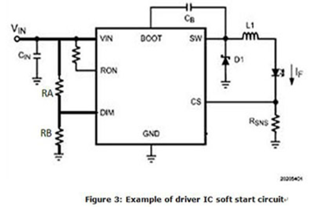
DIM PIN is the startup pin for most PWM based driver. It can also be designated as EN (Enable). DIM (or Enable) is at 0V the internal connection to SW pin will be open. When the DIM voltage reaches 1.5V (Typ), the IC will Turn ON. To set the Vstart for the DRIVER IC: Vstart = (VDIM/RB) x (RA+RB). The general rule is to set the Vstart at 5~10% higher than the total LED forward voltage.
LDD/LDH series comprises switching components; series or parallel connection will damage these switching components.
First of all. Determine the driving method of LED lamp. If the lamp is driven by constant current, forward current shall be within specification. On the contract, if it’s driven by constant voltage, then user must check if they are using the right product to dim the LED lamp, such as PWM/IDLV/ODLV series.
MEAN WELL’s specification shows the absolute values which were verified during design quality verification tests. Those condition are guaranteed by manufacture from quality and warranty perspectives.
When certifying a power supply according to a certain norm, there is normally a requirement described in this standard a certain tolerance which must be considered. (See also FAQ: Why Is The Input Voltage On The Label Different From The Input Voltage In The Spec? For Example, The Specification Shows Is 88~264 VAC While The Label On The Power Supply Says That It Is 100~240VAC?)
The specification shows what is possible, the report and label of the power supply shows what is approved by the certifying body according to the standards.
Besides the difference due to tolerance there might also be another reason why the specification and label/test report show a different temperature. For example, if the power supply needs to be derated at a low voltage input such as 100VAC, the label and test report might show the max temperature at full load based on this low input.
Different standards might have different tolerance requirements and different ranges this could mean that the most conservative value, or multiple values will show up on the label of the power supply.
MEAN WELL has incorporated dust proofing and waterproofing into the majority of its LED power supply design. Mainly based on the international standard IEC60529, detailed descriptions can be found in the following table:
(Note: PSUs with IP64 rating or above are suitable for indoor or outdoor applications in sheltered locations)
IP xy protection level
| Degree of protection, foreign bodies (x) | Degree of protection, moisture(y) |
| 0. Not protected 1. Solid foreign object (>50mm) 2. Solid foreign object (>12mm) 3. Solid foreign object (>2.5mm) 4. Solid foreign objects of 1,0mm diameter and greater 5. Amount of dust that would interfere with normal operation Dust tight | 0. Not protected 1. Vertically falling water drop 2. Vertically falling water drop when enclosure is tilted up to 15 degrees 3. Water sprayed at an angle up to 60o on either side of the vertical 4. Water splashed against the component from any direction 5. Water projected in jets from any direction (12.5 liter/minute) 6. Water projected in powerfil jets from any direction (100 liter/minute) 7. Temporary immersion in water ( 1 meeter from the surface of the water for 30 minutes) 8. Continuous immersion in water, or as specified by the user / manufacture |
*IP64-IP66 level products are suitable for damp indoor or sheltered outdoor environment. For actual installation limitations, please refer to the corresponding IP level tests.
*All products cannot be continuously submerged in water.
*The definition of IP68 by MEAN WELL: Immerse a unit under test in 1 meter below the surface of the water, tested with a dynamic condition where 12-hour AC on; 12-hour AC off.
Test duration: 1 month.
MEAN WELL’s DMTBF can be found on www.meanwell.com
Please note that the DMTBF is not for every model available. Mostly this information is available for the LED drivers and our latest product releases.
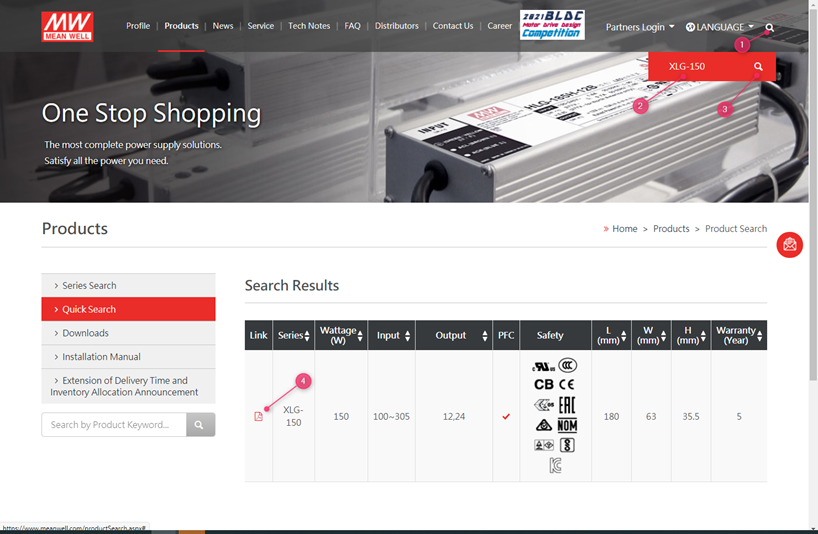
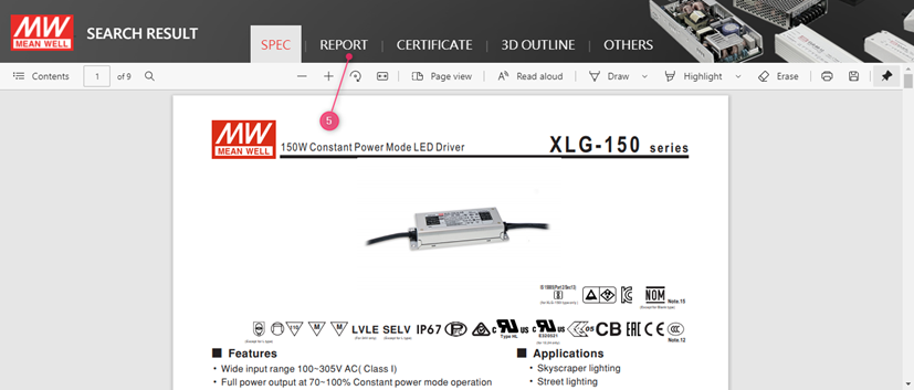
1. Use the search function on the website to find the right product
2. Fill in the series number in the search field (do not include the last extensions such as -12 in XLG-150-12)
3. Click the search button
4. Click on the PDF icon to open the specification
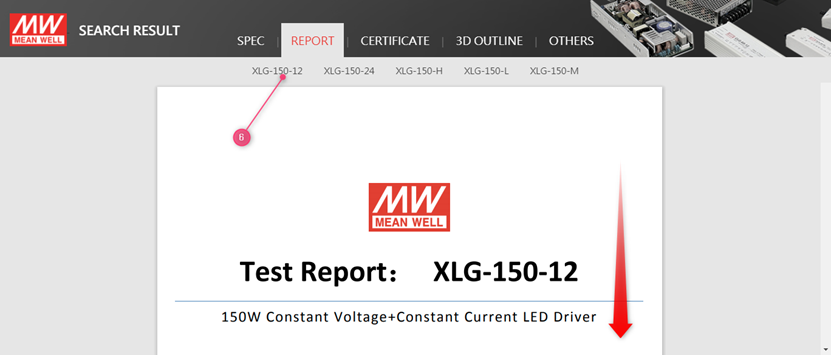
5. Click on report
6. Click on the model and scroll down:
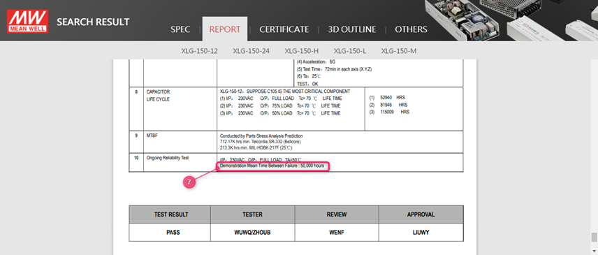
7. The DMTBF is shown on the last page of the report in the chapter Reliability test
LED Drivers are recommended operate at full load as long as it observes the working temperature specified in the datasheet, which means Tc measurement results should be equal to or less than the stated Tc in the datasheet. 5 years warranty complies as long as drivers operate within working Temperature and Tc. Limit as well.
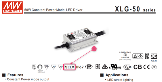
No, they are different. SELV means the LED driver will use a safety isolating transformer with double or reinforced insulation and the output voltage shall not exceed 120Vdc.
This is good for the end product safety certified if the LED driver with SELV output.
The definition of SELV was defined in the IEC 60950 standard but it is not defined in the IEC 62368 standard. This has been replaced with the ES1 Energy sources definition.
The definition of SELV is still applicable to the 61347-2-13 standard. In this standard it is that a LED driver will use a safety isolating transformer with double or reinforced insulation and the output voltage shall not exceed 120Vdc.
In the specification MEAN WELL’s 61347-2-13 certified LED drivers are marked with the SELV symbol in the case that the SELV requirements are fulfilled: