How to select the correct
MEAN WELL Charger & Lithium Battery
In recent years, the world has witnessed a significant shift toward sustainable energy solutions, with lithium-ion batteries emerging as a cornerstone of this transformation. From powering electric vehicles to storing renewable energy, lithium batteries have become increasingly vital in our quest for cleaner, more efficient energy systems.
Lithium batteries play a crucial role in modern energy storage and power solutions. Among various lithium-ion chemistries, two major types are NMC (Nickel Manganese Cobalt) and LFP (Lithium Iron Phosphate). Both have unique properties that make them suitable for different applications in industrial, consumer electronics, electric vehicles (EVs), and renewable energy storage. Today, MEAN WELL Europe offers a complete solution with a smart charger and lithium battery pack. By understanding every customer’s needs, we provide standard and personalized solutions.
We invite you to join us in exploring lithium batteries. We will uncover how these remarkable energy storage devices are changing the way we live and work and influencing the global transition to a more sustainable energy landscape.
Batteries offered by MEAN WELL Europe
Nowadays, the dynamics of the energy sector are rapidly changing, and the electrification process is accelerating. MEAN WELL Europe has expanded its product offering by including IoT-connected lithium batteries, which are made in Europe.
Here is the Lithium Battery offering from MEAN WELL Europe.


Advance Battery
Coming soon
Part 1: Batteries
1.1 How does a Battery work?
A battery has 2 poles, a positive and a negative pole, depending on whether you charge or discharge the battery, a reaction takes place in which electrons move from the positive to the negative side.
This effect is called a redox reaction (reduction-oxidation), in which the electrons are released from the cathode (reduction) and bind to the anode via an electrochemical reaction (oxidation). This creates a potential difference and electrode current, which can be used to drive a user, such as an electric motor.
These anode and cathode have the largest possible surface area and therefore consist of layers or are rolled up in a cell. The cell contains electrolyte in which the electrons can move freely from the anode to cathode.
1.2 Types of batteries
Basically, there are 3 types of battery, these types are divided into subcategories.
- Lead Batteries: divided into AGM and GEL
- Lithium Batteries: divided into NMC, LiFePO4, and the rest.
- The rest: divided into NiCd and NiMH, among others.
1.3 Lead-acid Batteries
For years, these were the most common batteries worldwide. Most are of the AGM (Absorbed Glass Mat) or GEL type.
With the latter, the electrolyte is incorporated in a kind of gel. The advantages of AGM batteries are the higher discharge currents than what is possible with gel. Because the electrolyte in gel batteries is processed in a gel, the electrons can move less freely. An advantage about GEL batteries is that you can usually mount them in multiple positions (such as upside down), which is usually not possible with AGM batteries.
These batteries can usually be discharged much deeper on a regular basis without high levels of chemical wear. A term you will also encounter is SLA, which means sealed lead acid and does not mean anything other than that these batteries are completely closed and cannot be refilled with electrolyte, which also applies to MF (maintenance free).
1.4 Lithium Batteries
Here we only discuss about NMC and LiFePO4 batteries. There are many other types of batteries that are based on lithium. NMC, or Nickel Manganese, Cobalt Oxide is a very popular chemical compound, commercially strong due to the favourable cost of ownership.
The NMC cells can be supplied as Polymer (LiPo) in the form of a rectangular so-called “pouch cell” and in a cylindrical shape such as the very popular 18650 cell shape, they are then called lithium ion (li-ion) cells. The disadvantage of LiPo cells is the higher initial costs and the lack of a CID (Current Interrupt Device), interrupts the circuit if the cell temperature is too high. This could, for example, occur during charging if the cell is broken. The CID is incorporated in the positive pole of the cell.
LiFePO4 basically has a longer lifespan than NMC due to the lower wear rate, but because the energy density and nominal voltage are lower, you need more cells to achieve the same power as NMC cells. This results in a higher cost price and a larger and heavier battery than what is possible with NMC. The positive point of LiFePO4 beyond its lifespan is the safety attributed to the cells.
1.5 Voltage (V)
Lead-acid batteries have a nicer linear decrease in voltage during use than lithium. Lithium has a flatter curve, roughly between 10% and 90% of the discharge time.
How do we arrive at the voltages indicated on a battery?
To do this, it must first be explained what exactly “nominal voltage” means. This nominal voltage is the average voltage of the battery (the voltage of a battery therefore slowly decreases during consumption). This average voltage is used as the calculation voltage and is called the nominal voltage.
You can calculate this nominal voltage by multiplying the number of cells in series by the nominal cell voltage below.
- NMC (Li-ion/LiPo) 3.6/3.7V
- LiFePO4 3.2V
- Lead acid AGM/GEL 2.0V
Now we come to the voltage indicated on a battery or charger, which is usually an approximation of the nominal battery voltage. So for which type of battery the charger is suitable. This is usually correct with lead/batteries. There are more differences and creative approaches with lithium batteries because the older lead-acid batteries are taken as a reference. For example, 12V can be made very nicely with 2V nominal cells, but with 3.6V Li-ion cells this is of course not possible and 3S or 4S is often used, both of which are called a 12V battery, which is of course not entirely correct.
When a very high power is required from a battery, the voltage of the battery drops at that moment, this is a phenomenon called voltage drop. This effect is caused by the resistance in the battery, so much energy is required from the battery that the redox reaction does not go fast enough. This occurs, for example, when a starter motor in a combustion engine is activated, the required current is so high that the voltage (temporarily) drops.
1.6 Capacity (Ah or Wh)
The capacity of a battery, also known as ampere hours (Ah), is determined by the total surface area of the anode and cathode per cell and how many of these cells are in parallel.

Suppose the cells in the above diagram have a capacity of 10Ah each, then the total capacity is 10*4= 40Ah. If the cells in this example have a voltage of 2V, the voltage of the entire system remains 2V.
Although capacity is often expressed in Ah, it is more accurate to express the capacity of a battery in Wh (Watt hours), or Voltage (V) * Ampere hours (Ah). This applies in particular to all batteries that are not based on lead acid or 1.5V penlites. For all other forms, including lithium, the voltage is often rounded to an equivalent lead-acid battery variant.
As an example; take a 12V 10Ah lead battery and a 12V 10Ah li-ion battery. You would initially say that the capacity of both batteries is the same. The capacity of the lead acid battery in Watt hours is 12*10 = 120Wh. For the lithium battery you must first know whether this is a 3S or 4S version to approach 12V, after all 3*3.6V = 10.8V and 4*3.6V = 14.4V. In other words, 12V cannot actually be simulated well with li-ion cells, yet it is offered. Let’s assume it’s 4S. Then the sum becomes 14.4V*10Ah is 144Wh. Basically more effective than the lead battery, and then we leave the Peukert effect aside.
Part 2: Chargers
2.1 How does a charger work?
A charger works by applying a certain voltage (V) and current (A) to a battery. That is why there is always a voltage and current indicated on the label of a charger. Please note that the current of a charger is indicated in A of amperes, so this is slightly different from the capacity of a battery, which is indicated in Ah (ampere hours).
You can calculate how quickly you can charge your battery with a particular charger based on the charging current A of the charger and the capacity in Ah of the battery. You can charge a 20Ah battery in about 4 hours with a 5A charger (20/5). – It is an approximation, depending on the charging phases that the charger has.
2.2 Which charger do I need?
Which charger you can use depends on which type of battery is used, so you all need different chargers for the batteries below:
- NMC (li-ion/LiPo)
- LiFePO4
- Lead/acid AGM
- Lead/acid GEL
The charging characteristic for all the above batteries is CC/CV, which means constant current/constant voltage. In other words, first, it is charged with a constant current (the current indicated on the charger), then with a constant voltage. While this voltage is maintained, the current drops to the charger’s cut-off point. For different types of batteries, there are different specified charging currents at that point.
Please see below; this is a typical CC/CV charging curve for 2/3 stage charging curves. It depends on the characteristics of the battery that you are using. This is the MEAN WELL spec of NPB-750 for your reference.

In addition to this 1st phase (CC) and 2nd phase (CV), MEAN WELL smart chargers have additional phases depending on whether it is a lead or lithium charger (2 or 3-stage selectable via DIP S.W on panel or set via SBP-001, Intelligent Battery Charging Programmer). For example, lead-acid chargers have a float mode as the 3rd phase, in which the batteries are kept at a fixed voltage with a small current. The lithium chargers have a “rest phase” as a 3rd phase in which the voltage of the battery drops. If the voltage falls below a preset level, the charger switches to another phase, which is known as a topping charge.
The correct charging voltage and current are essential for safely charging a battery. You have to calculate the correct charging voltage yourself if you know how many cells in the battery are in series. Each chemical composition has its own charging voltage per cell. Here are the (maximum) charging voltages per composition:
- NMC (Li-ion/LiPo) 4.2V (sometimes 4.1V)
- LiFePO4 3.65V
- Lead/acid AGM 2.37V-2.45V
- Lead/acid GEL 2.41V-2.45V
A Li-ion battery with a nominal voltage (the average battery voltage) of 48V with 13 cells in series (13S) therefore requires a charging voltage of 54.6V.
The other factor besides charging voltage is the charging current. This depends on what the battery can handle. The higher this current, the faster you can charge. It is recommended not to charge a battery or product faster than originally indicated. The data sheet of a battery often states the maximum current allowed. We strongly recommend always staying well below these maximum values.
2.3 What does the voltage indicated on the charger mean?
This is the nominal voltage, or in the case of lithium batteries often the rounded nominal voltage but it will lead to different results of different Wh. See this in Part 1: Batteries, 1.6 Voltage. Different devices require different voltages to charge properly, so it’s important to use a charger with the correct voltage to avoid damaging the device.
2.4 Power of a charger
You can calculate the power of a charger by multiplying the charging voltage by the charging current. In the case of 42V charging voltage and 5A charging current, you are at 210 Watts. So you will have to use a MEAN WELL smart charger of the 240Watt type.
The MEAN WELL chargers are available for different capacities, use different charger series for different application requirements.
Please see below for MEAN WELL charger offering.


2.5 Benefits of using a lithium battery with BMS
- Safety: BMS helps prevent overcharging, over-discharging, and overheating, which can improve the overall safety of the battery system.
- Extended Battery Life: The BMS can help optimize the charging and discharging cycles, which can extend the lifespan of the lithium battery.
- Efficiency: BMS helps monitor and regulate the flow of energy, ensuring that the battery operates at its most efficient levels.
- Performance Optimization: BMS can enhance the performance of the battery by maintaining consistent power output and protecting it from damage due to misuse or environmental factors.
- Monitoring and Diagnostics: BMS provides real-time monitoring of the battery’s health, allowing users to identify any issues promptly and take corrective actions.
- Balancing cell voltages: ensure that all cells are charged equally. This helps to extend the battery life and improve its performance.
- Analysing battery data: collect from the sensors to determine the battery’s state and condition and provide real-time information about the battery’s performance
2.6 MEAN WELL “Smart Charger + Lithium Battery”
- Screw mount type of smart charger
| MEAN WELL Charger | Number of Lithium Battery | |
| a | 1pc of NPB-450-48 or NPB-750-48 |
|
| b | 1pc of NPB-1200-48 |
|
| c | 1pc of NPB-1700-48 |
|
| d | 1pc of RPB-1600-48CAN |
|
| e | 1pc of RPB-1600-48CAN |
|
* The charging time depends on the amount of charge current with the selected charger
* C version battery incorporates a connector of M12 (A-coded/5pins), for CANBus communication
* Please contact your local MEAN WELL representative for accessories
* The recommended number of battery is only for reference. Please perform the overall evaluation with the final system.
| No CANBus
Battery-pack has built-in BMS, you can connect it to a power supply(constant voltage) if you only use one battery. |
 |
| With CANBus – M12/A-coded/ 5 pins
It is highly recommended to use this version with CANBus to optimize the charge/discharge current if you connect batteries in parallel |
 |
- IP6X solution
| MEAN WELL Charger | Number of Lithium Battery | |
| a | 1pc of HEP-600C-12 |
|
| b | 1pc of HEP-600C-24 |
|
| c | 1pc of HEP-600C-48 |
|
| d | 1pc of HEP-1000-24W(CCAN) |
|
* The charging time depends on the amount of charge current with selected charger
* C version battery incorporates a connector of M12 (A-coded/5pins), for CANBus communication
* Please contact your local MEAN WELL representative for accessories
* The recommended number of battery is only for reference. Please perform the overall evaluation with the final system.
CONCLUSION
MEAN WELL EUROPE created the platform of one-stop solution for lithium battery and smart charger to help you to shorten the development time & give the added value on your system design. This platform provides many advantages, you will benefit from quick response and the local technical support in Europe for both battery and charger/power-supply. It’s an approach that seeks to optimize the balance between cost and quality from your perspective, to make better decisions about what are the best investments for success.
MEAN WELL has various types of smart chargers and power supplies, from 30W up to 3200W. The lithium battery-pack can be able to communicate with the smart charger via the optimized interface to achieve the excellent performance in the entire solution that customer needs.
Contact us if you have questions on selecting our batteries or chargers.
Learn more about Charger & Lithium Battery
Explore our blog for insightful technical notes about Charger & Lithium Battery Applications.
Got questions?
Look at the section below to find the most frequently asked questions (with answers)
we received in Charger & Lithium Battery Applications.
The GTIN number can be found directly on the www.meanwell.com:

Internally, IRM series has the following AC fuses, which are implemented on AC/L input:
| IRM-01/02/03 | T1A/L300V |
| IRM-05/10/15/20/30 | T2A/L300V |
| IRM-45/60 | T2.5A/L300V |
| IRM-90 | T3.15A/L300V |
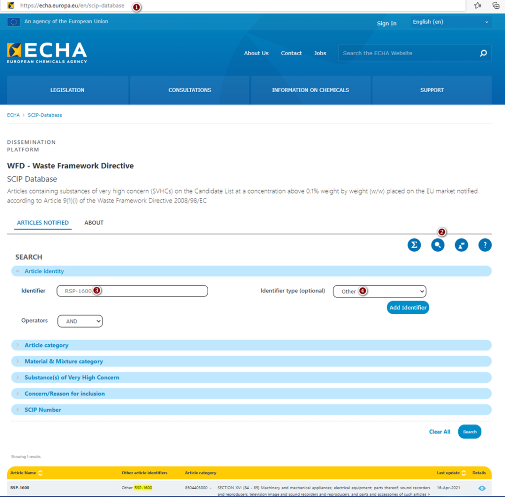
Yes, MEAN WELL products are registered in SCIP. To get such information for specific power supply, please follow the steps below:
- Go to https://echa.europa.eu/en/scip-database
- Under SEARCH option, choose „Article Identity” and write down model name e.g. RSP-1600.
- As “Identifier type (optional)”, please chose “Other”
- Click “Search” button
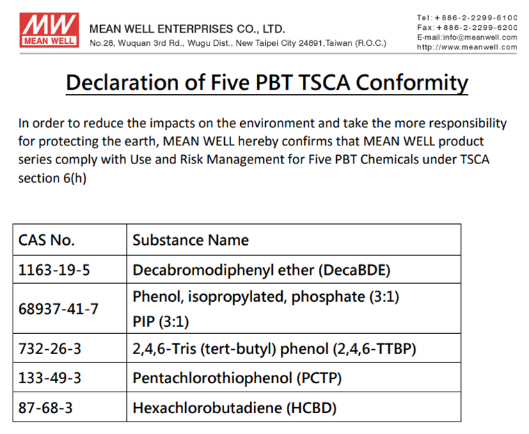
The declaration of Five PBT TSCA Conformity can be found on the last page of Installation Manual e.g. below:
Find the latest news in the MEAN WELL APP


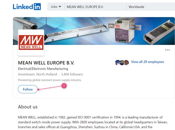
You can follow us on LinkedIn:

Go to:
https://www.linkedin.com/company/meanwell-europe-b-v-/
1. Click follow
And you could install our APP see our FAQ “How to subscribe to MEAN WELL’s newsletter?”
MEAN WELL’s distributor information can be found on Distributor Network-MEAN WELL Switching Power Supply Manufacturer
- Click on the region that you are located
- Select the country you are in
- Click on the search button
- Scroll down to see our local distribution channels
- Look for the distributor with a tick for the product group that you are looking for

MEAN WELL has the largest distribution network for serving your small and medium demand Power Supplies. You can find all MEAN WELL’s distribution channels on Distributor Network-MEAN WELL Switching Power Supply Manufacturer.
OEM’s which have no sales channel for MEAN WELL products yet can contact us via the “Contact Us” form on this website.
MEAN WELL’s discontinued product schedule and End of Life products are normally updated 2 times per year, in January and in July and are published on www.meanwell.com. See FAQ “Where can I find MEAN WELL’s discontinued product schedule and End of Life information? “
The normal procedure for E.O.L. is:
- The product or series is announced in the Discontinued product list in January or July and announced as NRND (Not Recommend for New Design)
- 6 months later the lead time of the product or series will increase +30 days, the price will increase as well.
- Another 6 months later, the lead time will increase another +30 days (so + 60day compared to the original lead time), the price will increase again.
- Another 6 months later, the lead time will increase another +30day (so +90 days compared to the original lead time) and the price will increase again and additionally there will be a MOQ of 200pcs (and steps of 100 for higher quantities)
- After another 6 months the last buy is announced on the website. This will be the last opportunity to place an order for this product or series.
In total MEAN WELL’s End of Life, procedure will take 2 years. However, there are situations for instance that certification is expired, or some components can no longer be obtained by the market which will force to accelerate the EOL schedule. Therefore, it is always highly recommended from the moment that a product is on the discontinued list to design in one of our new generation products. If need any advice to this, please use the “Contact Us” function on this website.
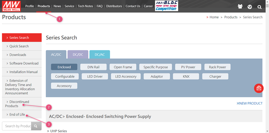
MEAN WELL’s discontinued product schedule and End of Life products are normally updated 2 times per year, in January and in July. To see the full list, go to www.meanwell.com
1. Click on products
2. Click on Discontinued products for the schedule for the EOL schedule
Click on EOL for the MEAN WELL products which are End Of Life
You can use the “Contact Us” function on this website
MEAN WELL’s website provides you all the basic information about our Power Supplies. This includes company news, product announcements, ISO certificates, Specifications, test report, Certificates, ROHS declarations, Reach declarations and many more.
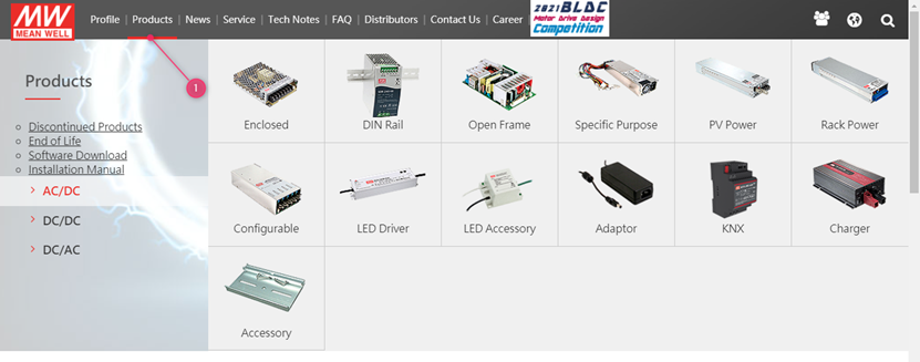
MEAN WELL’s products can be found on www.meanwell.com
1. Click on products and select the product category
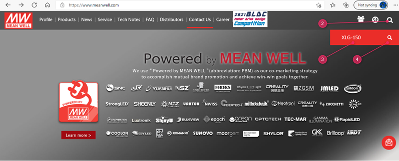
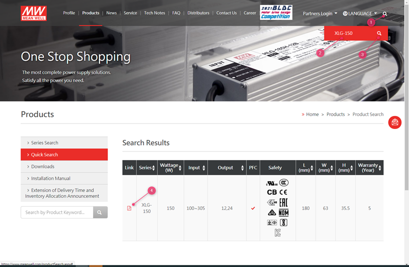
Or in case you already have a part number, you can use the search function on the website:
2. Use the search function on the website to find the right product
3. Fill in the series number in the search field (do not include the last extensions such as -12 in XLG-150-12)
4. Click the search button
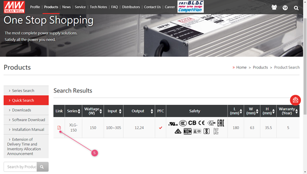
5. Click on the PDF icon to open the specification
MEAN WELL has several charger products, and we suggest choosing them first. Chargers would be more suitable since they are designed for charging applications. Safety and approvals should be taken into account based on the final application. If you are unable to find a proper model in our charger series, our LED CC models can be used as charger. Please choose suitable products after confirming the current and voltage specification on the datasheet of the battery.
All MEAN WELL chargers are preset for lead-acid batteries. For other products that can customize the charging curve (such as ENC / NPB series), customers can customize their charging curve depending on the charging and discharging characteristics of batteries. If you have other requirements, please use the contact us function on this website.
MEAN WELL has launched ENC, HEP-600C, GC, PA, PB, RPB and RCB series for battery charge applications (30~1000W). However, if these models cannot fulfill your requirements, there is an alternative solution. Power supplies with constant current limiting as overload protection are suggested. Charge current varies in battery percentage (full or flat), there is high possibility to trigger overload protection when battery is low, those with overload protection as hiccup or shutdown will stop charging the battery in low battery condition. Yet, using a power supply as charging purpose is considered as overload usage, modification is required. Please Contact Us for the request.
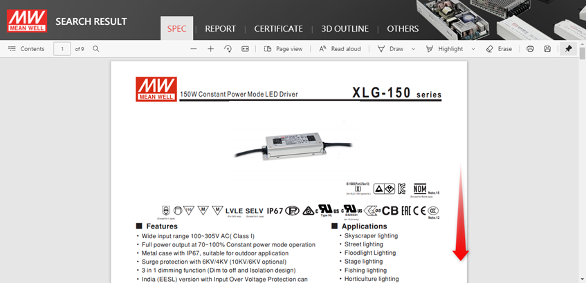
MEAN WELL’s Step files/ 3D files can be found on www.meanwell.com
- Use the search function on the website to find the right product
- Fill in the series number in the search field (do not include the last extensions such as -12 in XLG-150-12)
- Click the search button
- Click on the PDF icon to open the specification
- Click on 3D OUTLINE
- Click on the model XLG-150-3D to download the step file.

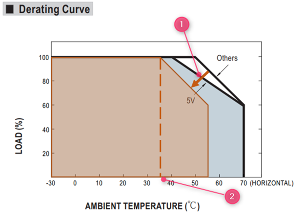
Yes, for power supplies certified >2000m please read the “note” in the spec.
In general, for unpotted models, a derating of 5°C/1000m has to be applied and for potted models, a derating of 3.5°C/1000m has to be applied.
For example LRS-75-24:
The datasheet shows:

The Note. 7 shows:

At 5000m the derating curve will need to move 15°C following the arrow (1)
At full load the maximum operating temperature at 5000m will be 35°C shown at (2)
Cooling fans have a relatively shorter lifetime (typical MTTF, Mean Time To Failure, of around 5,000-100,000 hours) compared with other components of power supply. As a result, changing operating method of the fans can extend the operation hours. The most common control schemes are shown as below:nnTemperature control: if the internal temperature of a power supply, detected by a temperature sensor, is over the threshold, the fan will start working at full speed, whereas, if the internal temperature is less than the set threshold, the fan will stop working or run at half speed. In addition, cooling fans in some power supplies are controlled by a non-linear control method whereby fan speed can be changed with different internal temperatures synchronously.nLoad control: if the loading of a power supply is over the threshold, the fan will start working at full speed, whereas, if the loading is less than the set threshold, the fan will stop working or run at half speed.
During safety verification process, the agency will use a stricter standard ±10% (IEC 62368 uses +10%, -10% for the product with AC input rated) of the input voltage range labeled on the power supply to conduct the test. So, operating at the wider input voltage range as specified on the spec. sheet should be fine. The narrower range of input voltage labeled on the power supply is to fulfill the test standard of safety regulation and make sure that users insert input voltage correctly.
PMBus full name is Power Management Bus is an open standard for digital power management. The physical layer is based on I2C, and PM Bus had a set of commands that specifically design for power supply industry. More information can be found in https://pmbus.org/
MEAN WELL Rack Power and intelligent power supply and chargers have optional PMBus solution for example: PHP-3500 and HEP-1000 further the RCP/RSP-1600, UHP-2500 and DPU-3200 have this optional available.
A Controller Area Network (CAN Bus) is a bus standard initially developed for vehicle designed to allow multi-master with priority control without a host computer. The latest version is CAN 2.0 which consists of part A and part B. CAN 2.0A is for standard format with 11-bit identifier, and CAN 2.0B is for extended format with 20-bit identifier. CAN Bus is widely used in Automotive and industrial automation. There are not only 1 but many higher layer protocol such as CANopen, DeviceNet and more.
MEAN WELL CAN Bus product support CAN 2.0B (ISO-11898) with baud rate 250Kbps
MEAN WELL offers optionally CAN bus for PHP-3500, HEP-1000, RCP/RSP-1600, UHP-2500 and DRP/DPU-3200 and DBR/DBU-3200.
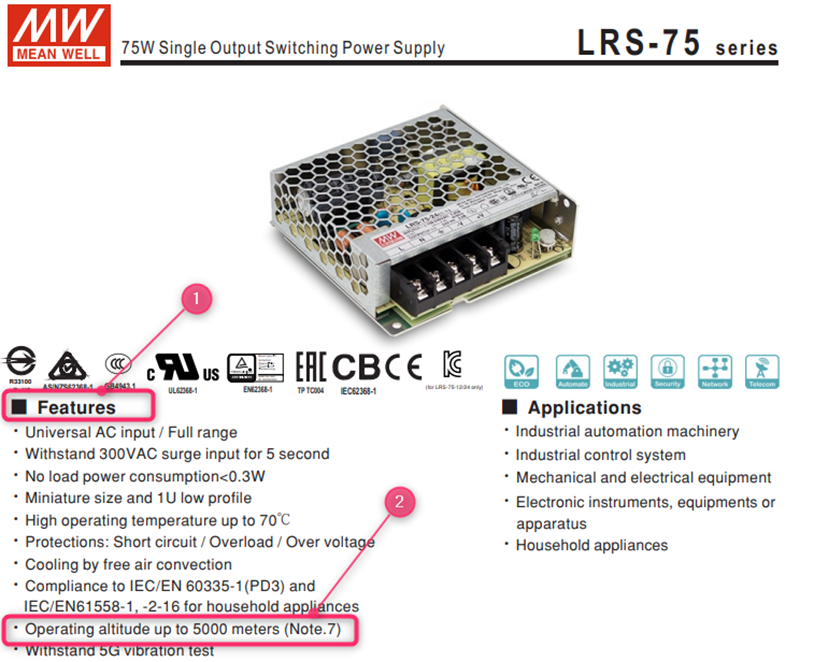
Most MEAN WELL power supplies are certified to be operated till 2000m. For some models the certification is valid for a higher altitude, this will be shown on the first page of the power supply under features (1)(2).
Please note that derating is needed at an altitude above 2000m. See FAQ “Do I need to derate my power supply when I used it over 2000m?”
MEAN WELL’s specification shows the absolute values which were verified during design quality verification tests. Those condition are guaranteed by manufacture from quality and warranty perspectives.
When certifying a power supply according to a certain norm, there is normally a requirement described in this standard a certain tolerance which must be considered. (See also FAQ: Why Is The Input Voltage On The Label Different From The Input Voltage In The Spec? For Example, The Specification Shows Is 88~264 VAC While The Label On The Power Supply Says That It Is 100~240VAC?)
The specification shows what is possible, the report and label of the power supply shows what is approved by the certifying body according to the standards.
Besides the difference due to tolerance there might also be another reason why the specification and label/test report show a different temperature. For example, if the power supply needs to be derated at a low voltage input such as 100VAC, the label and test report might show the max temperature at full load based on this low input.
Different standards might have different tolerance requirements and different ranges this could mean that the most conservative value, or multiple values will show up on the label of the power supply.
MEAN WELL’s component self-heating can be found on www.meanwell.com
1. Use the search function on the website to find the right product
2. Fill in the series number in the search field (do not include the last extensions such as -12 in XLG-150-12)
3. Click the search button
4. Click on the PDF icon to open the specification

5. Click on report

6. Click on the model and scroll down:

7. The temperature of the critical component can be found in the chapter Reliability Test under item 1 Temperature Rise Test
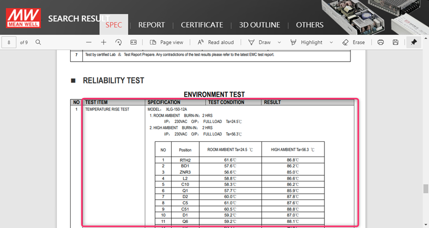
For more details about the component type for each position, please use the Contact Us function on this website.
MEAN WELL’s MTBF can be found on www.meanwell.com
1. Use the search function on the website to find the right product
2. Fill in the series number in the search field (do not include the last 3. extensions such as -12 in XLG-150-12)
3. Click the search button
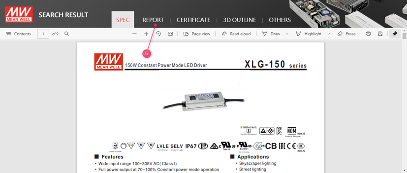
4. Click on the PDF icon to open the specification

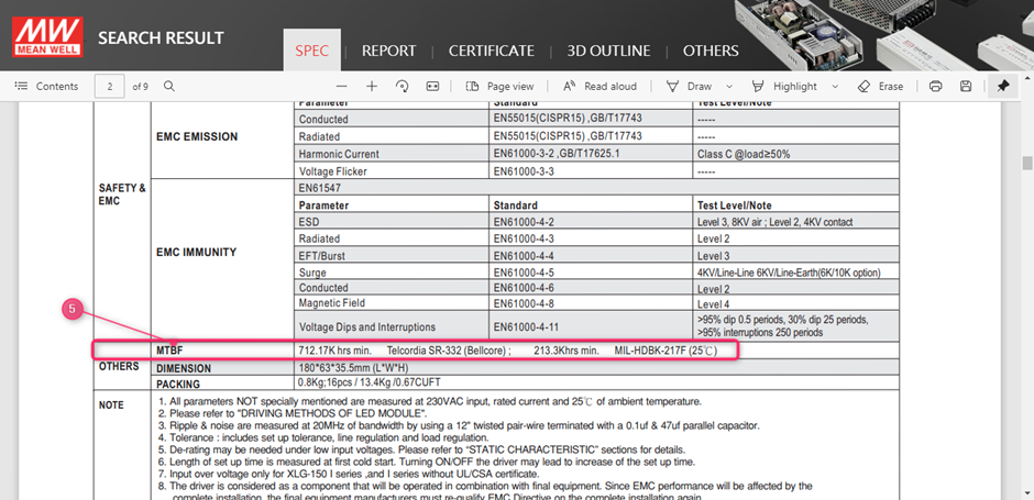
Scroll down in the specification to the bottom of the second page
5. Find the MTBF value in under others:
MEAN WELL’s capacitor lifecycle calculation can be found on www.meanwell.com
1. Use the search function on the website to find the right product
2. Fill in the series number in the search field (do not include the last extensions such as -12 in XLG-150-12)
3. Click the search button
4. Click on the PDF icon to open the specification

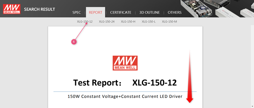
5. Click on report
6. Click on the model and scroll down:
7. The Capacitor life cycle calculation is shown on the last page of the report in the chapter Reliability test
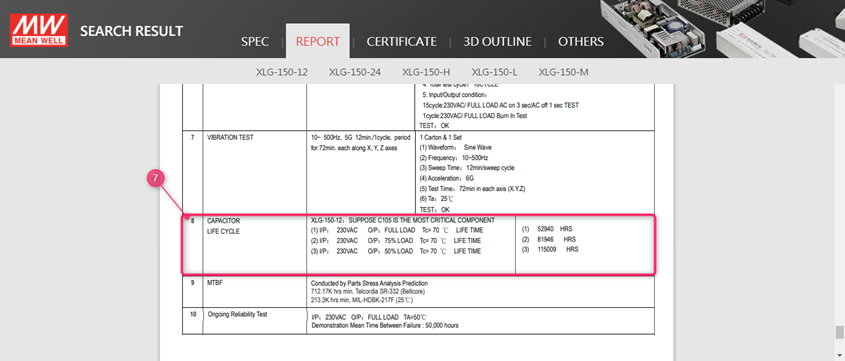
The Capacitor life cycle calculation is considered as the key indicator for the lifetime of the power supply. Please refer to the test report of the power supply on www.meanwell.com for the capacitor life cycle calculation.
As a rule of thumb, every 10dC increase the lifetime will be cut in half and vice versa for every 10dC decrease in temperature.
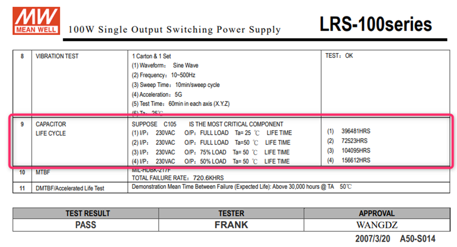
In the above example, if the power supply is used at 75dC at Ta 40dC, the estimated lifetime would be 2*104095 Hrs ~200K hrs.
In MEAN WELL’s specification you can find 2 derating curves, in below example the 300W open frame power supply: EPP-300
- The Derating Curve with the Ambient Temperature vs. Load
- The Derating Curve with the Input Voltage vs. Load

- In this Curve one can find that the maximum load of this power supply is 300W at 50dC when an external air flow of 20.5CFM is applied. For temperatures exceeding 50dC, 60dC for example additional derating need to be applied, in above case at 60dC the maximum load would be 225W. (50dC 300W, 70dC 150W => from 50dC to 60dC: 75W derating)
- In case this power supply would be used at 90VAC input, a derating of 80% must be applied. So, in previous example with the 20.5CFM forced air the max load would be 240W. In case of an ambient temperature of 60dC and a 90VAC input the maximum rated power would be 225W * 0.8 = 180W with 20.5CFM forced air.
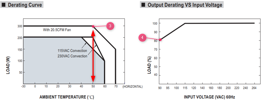
- If the power supply is used in an application without additional forced Air, the power supply will be derated to 200W till a maximum temperature of 50dC
- In case it will be powered by a 90VAC input the power supply has to be additionally derated to 80% of the 200W = 160W max
MTBF (Mean Time Between Failure) and Life Cycle are both indicators of reliability. MTBF can be calculated by two different methodologies, which are “part count” and “stress analysis”. The regulations, MIL-HDBK-217F Notice 2 and TELCORDIA SR/TR-332(Bellcore) are commonly used to calculate MTBF. MIL-HDBK-217F is a United States military standard, and TELCORDIA SR/TR-332(Bellcore) is a commercial regulation. MEAN WELL utilize MIL-HDBK-217F(Stress Analysis) as the core of MTBF. The exact meaning of MTBF is, after continuously using the power supply for a certain amount of time, the average time that the probability of proper operation is down to 36.8%(e-1=0.368). Currently MEAN WELL is adopting MIL-HDBK-217F, to predict the expected reliability through Stress Analysis (excluding fans); this MTBF means the probability of the product can continue the normal work after working continuously up to the calculated MTBF time is 36.8% (e-1=0.368). If the power supply is continuously used at double the MTBF time, the probability of proper operation becomes 13.5%(e-2=0.135.
DMTBF (Demonstrated Mean Time Between Failures) is a way of evaluating MTBF in a relatively short period of time based on accelerated deterioration (high stress, high temperature) tests under specific parameters and conditions. Please refer to the following equation for MTBF calculation.
This method compares to the previous methods, this calculation uses real test data to demonstrate the reliability of the power supply.
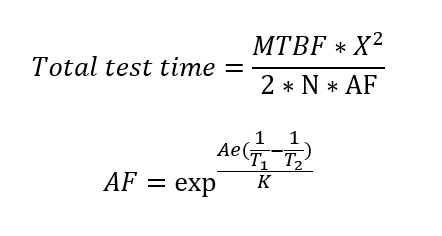
Where
MTBF: Mean Time Between Failure
- X2:Can be found in chi-square distribution
- N:Number of sampling
- AF:Acceleration factor, which can be derived from acceleration factor equation.
- Ae=0.6
- K(Boltzmann Constant)=(eV/k)
- T1:Rated temperature of specification. Note: Kelvin will be the unit use for calculation
- T2:The temperature that is used in the meaning of acceleration, and the chosen temperature could not result in physical change in materials.
Note: Kelvin will be the unit use for calculation.
Life Cycle (Capacitor Life Cycle) is found by using the temperature rise of electrolytic capacitors under maximum operating temperature to estimate the approximate life of the power supply. For example, RSP-750-12 MTBF=109.1K hours(25°C); electrolytic capacitor C110 Life Cycle=213K hours (Ta=50℃).
MEAN WELL considers the capacitor lifecycle calculation as the most important indicator for the estimated lifetime. The (D)MTBF is the main indicator for the reliability of the power supply. For more information please see: Investigation of The Lifetime & Reliability of Power Supply -MEAN WELL EUROPE Switching Power Supply
MEAN WELL’s safety reports, IEC reports and CB reports are not available online. In case you need these reports to validate your design with your certifying body, please contact your local MEAN WELL sales channel for support. If you are unable to get the support, please contact us via this website.
MEAN WELL’s User Manual can be found on www.meanwell.com
1. Go to products
2. Click on Installation Manual
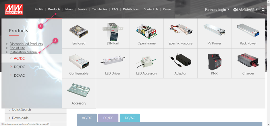
3. Scroll down to find the user manuals for the different product families.

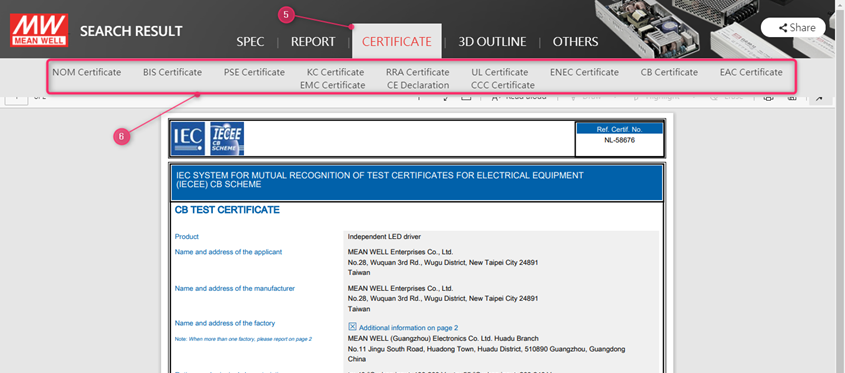
MEAN WELL’s Safety certifications can be found on www.meanwell.com
- Use the search function on the website
- Fill in the series number in the search field (do not include the last extentions suchs as -12 in XLG-150-12
- Click the search button

4. Click on the PDF Link
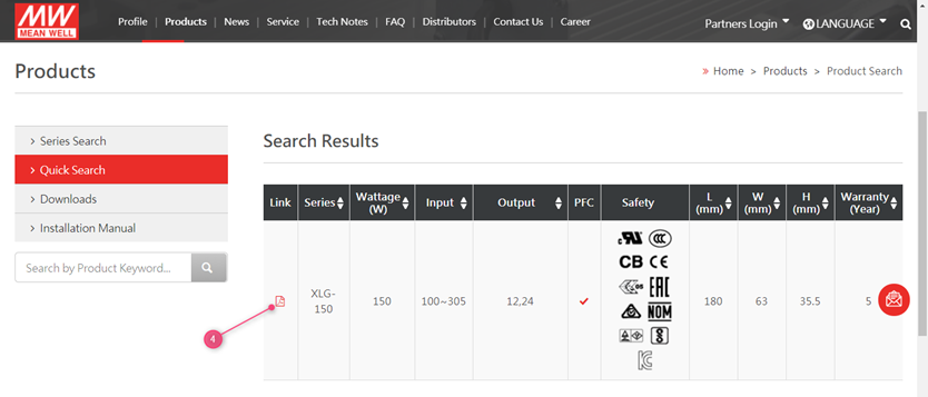
5. Click on the top on the certificate
6. All available certificates are shown and will show up once clicked upon
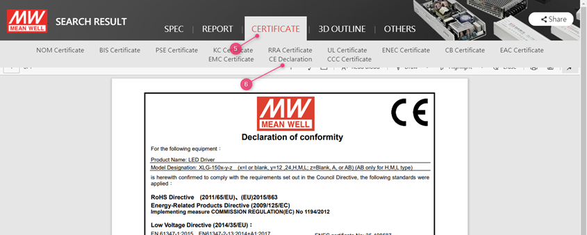
MEAN WELL’s CE declarations can be found on www.meanwell.com
- Use the search function on the website
- Fill in the series number in the search field ( do not include the last extentions suchs as -12
- Click the search button

4. Click on the PDF Link

5. Click on the top on certificate
6. Click on CE declaration
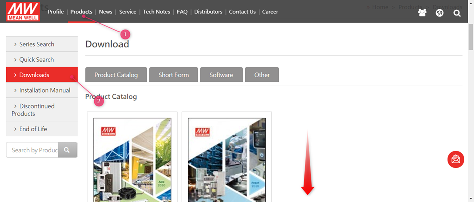
Select (1) Products followed by (2) downloads
MEAN WELL’s EMI test guide can be found on www.meanwell.com
Select (1) Products followed by (2) Downloads

After this scroll down to find the EMI testing of Power guide
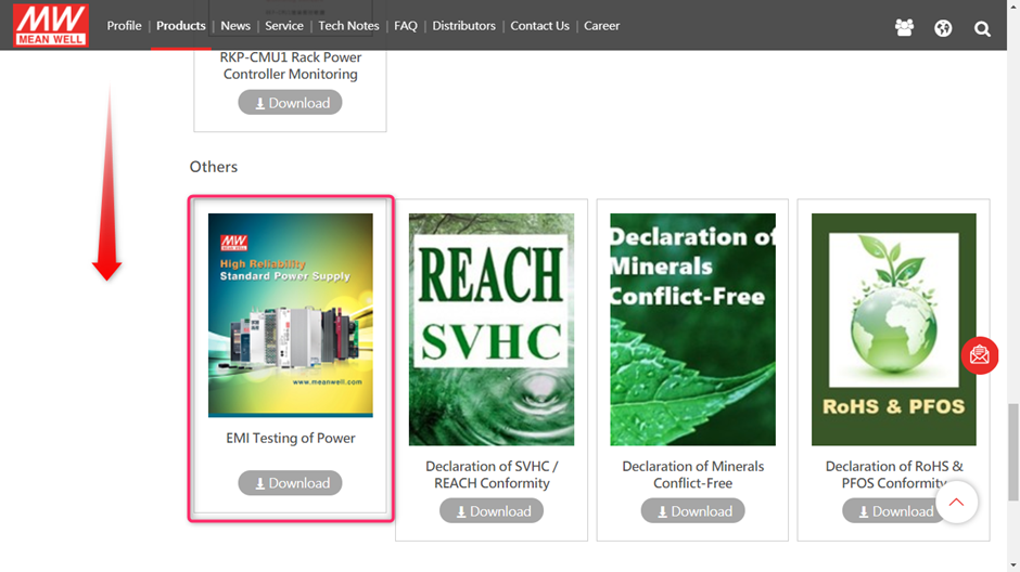
Or you can use this link to directly download the EMI testing guide:
EMI_statement_en.pdf
MEAN WELL’s RoHS and Reach statements can be found on www.meanwell.com
Select (1) Products followed by (2) Downloads:
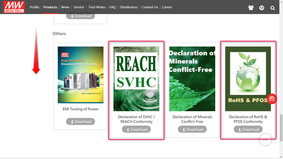
After this scroll down to find the RoHS declaration and Declaration of SVHC/ REACH conformity:
Or you can use the below links to download the declarations:
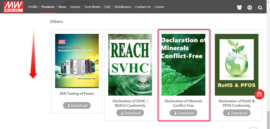
MEAN WELL’s Declaration of Conflict Free Minerals can be found on www.meanwell.com
Select (1) Products followed by (2) Downloads

After this scroll down to find the Declaration of Minerals Conflict Free
Or you can use this Link to directly download the EMI testing guide: